Next-Generation Firewall
Use Case: Advanced LSVPN Configuration with iBGP
Table of Contents
Use Case: Advanced LSVPN Configuration with iBGP
Advanced LSVPN configuration workflow using iBGP to securely connect up to 500
distributed office locations with primary and disaster recovery data centers.
| Where Can I Use This? | What Do I Need? |
|---|---|
|
|
This use case illustrates how GlobalProtect LSVPN securely connects distributed office locations
with primary and disaster recovery data centers that house critical applications for
users and how an internal border gateway protocol (iBGP) eases deployment and
upkeep. Using this method, you can extend up to 500 satellite offices connecting to
a single gateway.
BGP is a highly scalable, dynamic routing protocol that is ideal for hub-and-spoke deployments
such as LSVPN. As a dynamic routing protocol, it eliminates much of the overhead
associated with access routes (static routes) by making it relatively easy to deploy
additional satellite firewalls. Due to its route filtering capabilities and features
such as multiple tunable timers, route dampening, and route refresh, BGP scales to a
higher number of routing prefixes with greater stability than other routing
protocols like RIP and OSPF. In the case of iBGP, a peer group, which includes all
the satellites and gateways in the LSVPN deployment, establishes adjacencies over
the tunnel endpoints. The protocol then implicitly takes control of route
advertisements, updates, and convergence.
In this example configuration, an
active/passive HA pair of PA-5200 firewalls is deployed in the primary
(active) data center and acts as the portal and primary gateway.
The disaster recovery data center also has two PA-5200s in an active/passive
HA pair acting as the backup LSVPN gateway. The portal and gateways
serve 500 PA-220s deployed as LSVPN satellites in branch offices.
Both
data center sites advertise routes but with different metrics. As
a result, the satellites prefer and install the active data center’s
routes. However, the backup routes also exist in the local routing
information base (RIB). If the active data center fails, the routes
advertised by that data center are removed and replaced with routes
from the disaster recovery data center’s routes. The failover time
depends on selection of iBGP times and routing convergence associated
with iBGP.
The
following workflow shows the steps for configuring this deployment:
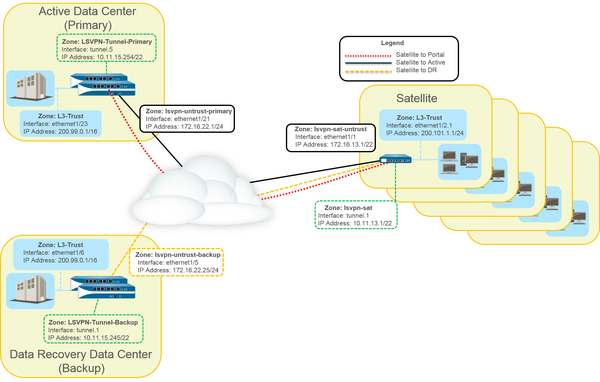
- Create Interfaces and Zones for the LSVPN.Portal and primary gateway:
- Zone: LSVPN-Untrust-Primary
- Interface: ethernet1/21
- IPv4: 172.16.22.1/24
- Zone: L3-Trust
- Interface: ethernet1/23
- IPv4: 200.99.0.1/16
Backup gateway:- Zone: LSVPN-Untrust-Primary
- Interface: ethernet1/5
- IPv4: 172.16.22.25/24
- Zone: L3-Trust
- Interface: ethernet1/6
- IPv4: 200.99.0.1/16
Satellite:- Zone: LSVPN-Sat-Untrust
- Interface: ethernet1/1
- IPv4: 172.16.13.1/22
- Zone: L3-Trust
- Interface: ethernet1/2.1
- IPv4: 200.101.1.1/24
Configure the zones, interfaces, and IP addresses on each satellite. The interface and local IP address will be different for each satellite. This interface is used for the VPN connection to the portal and gateway.On the firewall(s) hosting GlobalProtect gateway(s), configure the logical tunnel interface that will terminate VPN tunnels established by the GlobalProtect satellites.Primary gateway:- Interface: tunnel.5
- IPv4: 10.11.15.254/22
- Zone: LSVPN-Tunnel-Primary
Backup gateway:- Interface: tunnel.1
- IPv4: 10.11.15.245/22
- Zone: LSVPN-Tunnel-Backup
Enable SSL Between GlobalProtect LSVPN Components.The gateway uses the self-signed root certificate authority (CA) to issue certificates for the satellites in a GlobalProtect LSVPN. Because one firewall houses the portal and primary gateway, a single certificate is used for authenticating to the satellites. The same CA is used to generate a certificate for the backup gateway. The CA generates certificates that pushed to the satellites from the portal and then used by the satellites to authenticate to the gateways.You must also generate a certificate from the same CA for the backup gateway, allowing it to authenticate with the satellites.- On the firewall hosting the GlobalProtect portal, create the root CA certificate for signing the certificates of the GlobalProtect components. In this example, the root CA certificate is called CA-cert.Create SSL/TLS service profiles for the GlobalProtect portal and gateways. Because the GlobalProtect portal and primary gateway are the same firewall interface, you can use the same server certificate for both components.
- Root CA Certificate: CA-Cert
- Certificate Name: LSVPN-Scale
Deploy the self-signed server certificates to the gateways.Import the root CA certificate used to issue server certificates for the LSVPN components.Create a certificate profile.Repeat steps 2 through 5 on the backup gateway with the following settings:- Root CA Certificate: CA-cert
- Certificate Name: LSVPN-back-GW-cert
Configure GlobalProtect Gateways for LSVPN.- Select and click Add.On the General tab, name the primary gateway LSVPN-Scale.Under Network Settings, select ethernet1/21 as the primary gateway interface and enter 172.16.22.1/24 as the IP address.On the Authentication tab, select the LSVPN-Scale certificate created in 3.Select and select Tunnel Configuration. Set the Tunnel Interface to tunnel.5. All satellites in this use case connect to a single gateway, so a single satellite configuration is needed. Satellites are matched based on their serial numbers, so no satellites will need to authenticate as a user.On , define the pool of IP address to assign to the tunnel interface on the satellite once the VPN connection is established. Because this use case uses dynamic routing, the Access Routes setting remains blank.Repeat steps 1 through 5 on the backup gateway with the following settings:
- Name: LSVPN-backup
- Gateway interface: ethernet1/5
- Gateway IP: 172.16.22.25/24
- Server cert: LSVPN-backup-GW-cert
- Tunnel interface: tunnel.1
Configure iBGP on the primary and backup gateways and add a redistribution profile to allow the satellites to inject local routes back to the gateways.Each satellite office manages its own network and firewall, so the redistribution profile called ToAllSat is configured to redistribute local routes back to the GlobalProtect gateway.- Select and Add a virtual router.On Router Settings, add the Name and Interface for the virtual router.On Redistribution Profile, select Add.
- Name the redistribution profile ToAllSat and set the Priority to 1.
- Set Redistribute to Redist.
- Add ethernet1/23 from the Interface drop-down.
- Click OK.
Select BGP on the virtual router to configure BGP.- On , select Enable.
- Enter the gateway IP address as the Router ID (172.16.22.1) and 1000 as the AS Number.
- In the Options section, select Install Route.
- On , click Add a peer group with all the satellites that will connect to the gateway.
- On , Add the ToAllSat redistribution profile you created previously.
Click OK.Repeat steps 1 through 5 on the backup gateway using ethernet1/6 for the redistribution profile.Prepare the Satellite to Join the LSVPN.The configuration shown is a sample of a single satellite.Repeat this configuration each time you add a new satellite to the LSVPN deployment.- Configure a tunnel interface as the tunnel endpoint for the VPN connection to the gateways.Set the IPSec tunnel type to GlobalProtect Satellite and enter the IP address of the GlobalProtect portal.Select and Add a virtual router.On Router Settings, add the Name and Interface for the virtual router.Select and Add a profile with the following settings.
- Name the redistribution profile ToLSVPNGW and set the Priority to 1.
- Add an Interface ethernet1/2.1.
- Click OK.
Select , Enable BGP and configure the protocol as follows:- Enter the gateway IP address as the Router ID (172.16.22.1) and 1000 as the AS Number.
- In the Options section, select Install Route.
- On , Add a peer group containing all the satellites that will connect to the gateway.
- On , Add the ToLSVPNGW redistribution profile you created previously.
Click OK.Configure the GlobalProtect Portal for LSVPN.Both data centers advertise their routes but with different routing priorities to ensure that the active data center is the preferred gateway.- Select and click Add.On General, enter LSVPN-Portal as the portal name.On Network Settings, select ethernet1/21 as the Interface and select 172.16.22.1/24 as the IP Address.On the Authentication tab, select the previously created primary gateway SSL/TLS Profile LSVPN-Scale from the SSL/TLS Service Profile drop-down.On the Satellite tab, Add a satellite and Name it sat-config-1.Set the Configuration Refresh Interval to 12.On , add the serial number and hostname of each satellite device in the LSVPN.On , add the name and IP address of each gateway. Set the routing priority of the primary gateway to 1 and the backup gateway to 10 to ensure that the active data center is the preferred gateway.Verify the LSVPN Configuration.(Optional) Add a new site to the LSVPN deployment.
- Select to add the serial number of the new satellite to the GlobalProtect portal.Configure the IPSec tunnel on the satellite with the GlobalProtect portal IP address.Select to add the satellite to the BGP peer group configuration on each gateway.Select to add the gateways to the BGP peer group configuration on the new satellite.