Next-Generation Firewall
Configure a Logical Router
Table of Contents
Configure a Logical Router
Configure a logical router to enable routing for an Advanced Routing
Engine.
The firewall uses logical routers to obtain Layer 3 routes to other
subnets by you manually defining static routes or through participation in one or
more Layer 3 routing protocols (dynamic routes). The routes that the firewall
obtains through these methods populate the IP routing information base (RIB) on the
firewall. When a packet is destined for a different subnet than the one it arrived
on, the logical router obtains the best route from the RIB, places it in the
forwarding information base (FIB), and forwards the packet to the next hop router
defined in the FIB. The firewall uses Ethernet switching to reach other devices on
the same IP subnet. (An exception to one best route going in the FIB occurs if you
are using ECMP, in which case all equal-cost
routes go in the FIB.)
The Ethernet, VLAN, and tunnel interfaces defined on the firewall receive and forward
Layer 3 packets. The destination zone is derived from the outgoing interface
based on the forwarding criteria, and the firewall consults policy rules to identify
the security policies that it applies to each packet. In addition to routing to
other network devices, logical routers can route to other logical routers within the
same firewall if a next hop is specified to point to another logical router.
You can Configure Layer 3 Interfaces to participate with dynamic routing protocols (BGP, OSPF,
OSPFv3, or RIP) as well as add static routes. You can also create multiple logical
routers, each maintaining a separate set of routes that aren’t shared between
logical routers, enabling you to configure different routing behaviors for different
interfaces.
You can configure dynamic routing from one logical router to another by configuring a
loopback interface in each logical router, creating a static route between the two
loopback interfaces, and then configuring a dynamic routing protocol to peer between
these two interfaces. The firewall supports only one hop between logical routers.
For example, with logical routers A, B, and C, a route cannot go from A to B to C;
it would have to go from A to C.
Each Layer 3 Ethernet, loopback, VLAN, and tunnel interface defined on the firewall
must be associated with a logical router. While each interface can belong to only
one logical router, you can configure multiple routing protocols and static routes
for a logical router. Regardless of the static routes and dynamic routing protocols
you configure for a logical router, one general configuration is required.
In order to perform network routing, the Advanced Routing Engine requires you to
configure at least one logical router; there is no default logical
router. A logical router maintains a separate routing information base and keeps
routes from exposure to other logical routers. The number of logical routers supported for an Advanced
Routing Engine varies based on firewall model.
Before you can configure a logical router, you must Enable Advanced Routing.
Configure a Logical Router (PAN-OS)
Procedure for configuring a logical router in PAN-OS and Panorama.
- Select and Add a logical router by Name using a maximum of 31 characters. The name must start with an alphanumeric character, underscore (_), or hyphen (-), and can contain a combination of alphanumeric characters, underscore (_) or hyphen(-). No dot (.) or space is allowed.Add interfaces to the logical router.
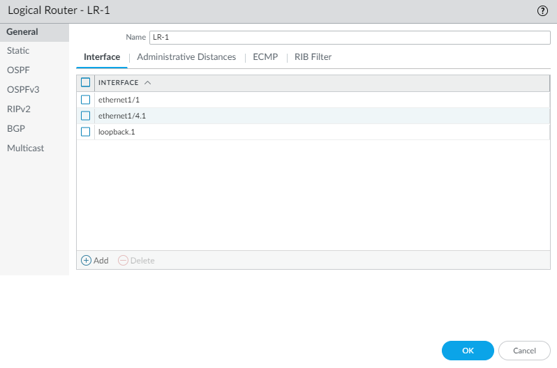
- While still on the Logical Router General tab, select the Interface tab.Add an interface to the logical router by selecting from the list of interfaces. An interface can belong to only one logical router. Repeat to add more interfaces, as in the following example for the logical router named LR-1:
![]() (Optional) Select Administrative Distances to change the global administrative distance (from the default setting) for various types of routes.
(Optional) Select Administrative Distances to change the global administrative distance (from the default setting) for various types of routes.![]()
- Static—Range is 1 to 255; default is 10.
- Static IPv6—Range is 1 to 255; default is 10.
- OSPF Intra Area—Range is 1 to 255; default is 110.
- OSPF Inter Area—Range is 1 to 255; default is 110.
- OSPF External—Range is 1 to 255; default is 110.
- OSPFv3 Intra Area—Range is 1 to 255; default is 110.
- OSPFv3 Inter Area—Range is 1 to 255; default is 110.
- OSPFv3 External—Range is 1 to 255; default is 110.
- BGP AS Internal—Range is 1 to 255; default is 200.
- BGP AS External—Range is 1 to 255; default is 20.
- BGP Local Route—Range is 1 to 255; default is 20.
- RIP—Range is 1 to 255; default is 120.
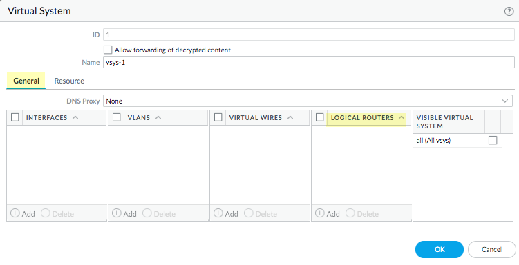
Click OK.(On a firewall supporting multiple virtual systems) Assign the logical routers to a virtual system.- Select and select a virtual system and General.Add one or more Logical Routers.Click OK.
![]() Click OK.(Optional) Configure ECMP for a logical router by navigating to , selecting a logical router, and then . Configure ECMP for a logical router much as you would for a virtual router on a legacy routing engine.ECMP is not supported for equal-cost routes where one or more of those routes has a virtual router or logical router as the next hop. None of the equal-cost routes will be installed in the Forwarding Information Base (FIB).Commit the changes.For a firewall with a pre-existing configuration, select and Reboot Device. Then log back into the firewall.(Optional) View Runtime Stats for a logical router.
Click OK.(Optional) Configure ECMP for a logical router by navigating to , selecting a logical router, and then . Configure ECMP for a logical router much as you would for a virtual router on a legacy routing engine.ECMP is not supported for equal-cost routes where one or more of those routes has a virtual router or logical router as the next hop. None of the equal-cost routes will be installed in the Forwarding Information Base (FIB).Commit the changes.For a firewall with a pre-existing configuration, select and Reboot Device. Then log back into the firewall.(Optional) View Runtime Stats for a logical router.- Select and for a specific logical router, select More Runtime Stats on the far right.To see the route tables for all protocols, on the Routing tab, select Route Table and Display Address Family: IPv4 and IPv6, IPv4 Only, or IPv6 Only.
![]() To see entries in the Forwarding Information Base (FIB), select Forwarding Table.Select Static Route Monitoring to see the static routes you are monitoring.Select the BGP tab and then Summary to see BGP settings.Select Peer to see BGP peer settings.Select Peer Group to see BGP peer group settings.Select Route and Display Address Family: IPv4 and IPv6, IPv4 Only, or IPv6 Only to see the attributes of BGP routes.Access the CLI to view advanced routing information. The PAN-OS CLI Quick Start lists the commands in the CLI Cheat Sheet: Networking.
To see entries in the Forwarding Information Base (FIB), select Forwarding Table.Select Static Route Monitoring to see the static routes you are monitoring.Select the BGP tab and then Summary to see BGP settings.Select Peer to see BGP peer settings.Select Peer Group to see BGP peer group settings.Select Route and Display Address Family: IPv4 and IPv6, IPv4 Only, or IPv6 Only to see the attributes of BGP routes.Access the CLI to view advanced routing information. The PAN-OS CLI Quick Start lists the commands in the CLI Cheat Sheet: Networking.Configure a Logical Router (SCM)
Procedure for configuring a logical router in Strata Cloud Manager.- Log in to Strata Cloud Manager.Select and select the Configuration Scope where you want to create the logical router.You can select a folder or firewall from your Folders or select Snippets to configure the logical router in a snippet.The number of logical routers supported varies based on the firewall model. If you create multiple logical routers for a folder or snippet, verify that the firewalls associated with the folder or snippet support the number of logical routers you configure.Add Router.Enter a descriptive Name.A maximum of 31 characters are supported. The name must start with an alphanumeric character, underscore (_), or hyphen (-) and can contain a combination of alphanumeric characters, underscore (_), or hyphen (-). A dot (.) or space isn’t supported.(Optional) Configure Equal Cost Multiple Path (ECMP) processing.Enabling this setting enables the firewall to use up to four equal-cost routes to the same destination.
- Enable ECMP.Set the ECMP Max Path to specify the maximum number of equal-cost paths that can be copied from the RIB to the FIB.Default is 2. 2, 3, or 4 are supported.Enable Symmetric Return of packets from server to client.Select Symmetric Return to cause return packets to egress out the same interface on which the associated ingress packets arrived. That is, the firewall will use the ingress interface on which to send return packets, rather than use the ECMP interface. The Symmetric Return setting overrides load balancing. This behavior occurs only for traffic flows from the server to the client.Enable Strict Source Path o ensure that IKE and IPSec traffic originating at the firewall egresses the physical interface to which the source IP address of the IPSec tunnel belongs.When you enable ECMP, IKE and IPSec traffic originating at the firewall by default egresses an interface that an ECMP load-balancing method determines. Alternatively, you can ensure that IKE and IPSec traffic originating at the firewall always egresses the physical interface to which the source IP address of the IPSec tunnel belongs, by enabling Strict Source Path. You would enable this function when the firewall has more than one ISP providing equal-cost paths to the same destination. ISPs typically perform a reverse Path Forwarding (RPF) check (or a different check to prevent IP address spoofing) to confirm that traffic is egressing the same interface on which it arrived. Because ECMP would choose an egress interface based on the configured ECMP method (instead of choosing the source interface as the egress interface), that wouldn’t be what the ISP expects and the ISP could block legitimate return traffic. In this case, enable Strict Source Path so that the firewall uses the egress interface that is the interface to which the source IP address of the IPSec tunnel belongs, the RPF check succeeds, and the ISP allows the return traffic.Specify the load-balance Action for the logical router.
- Balanced Round Robin (default)—Uses round-robin among the ECMP paths and rebalances paths when the number of paths changes.
- IP Hash—Use a hash of the source and destination IP addresses to determine which ECMP route to use.If you select this option, can select to Use Source Address Only and Use Source/Destination port for hash.
- IP Modulo—Uses a hash of the source and destination IP addresses in the packet header to determine which ECMP route to use.
- Weighted Round Robin—Uses round-robin and a relative weight to select from among ECMP paths.
Add an Interface.Repeat this step to add as many Layer 3, loopback, and tunnel interfaces as needed.Save.