GlobalProtect
Create Interfaces and Zones for GlobalProtect
Table of Contents
Create Interfaces and Zones for GlobalProtect
Configure interfaces and zones for GlobalProtect by setting up Layer 3 interfaces for
the portal and gateways and assigning them to a zone. Create logical tunnel interfaces,
secure administrative access, and create security policies for traffic flow.
| Where Can I Use This? | What Do I Need? |
|---|---|
|
|
You must configure the following interfaces
and zones for your GlobalProtect infrastructure:
- GlobalProtect portal—Requires a Layer 3 or loopback interface for the GlobalProtect apps’ connection. If the portal and gateway are on the same firewall, they can use the same interface. The portal must be in a zone that is accessible from outside your network, such as a DMZ.
- GlobalProtect gateways—The interface and zone requirements for the gateway depend on whether the gateway you're configuring is external or internal, as follows:
- External gateways—Requires a Layer 3 or loopback interface and a logical tunnel interface for the app to establish a connection. The Layer 3/loopback interface must be in an external zone, such as a DMZ. A tunnel interface can be in the same zone as the interface connecting to your internal resources (for example, trust). For added security and better visibility, you can create a separate zone, such as corp-vpn. If you create a separate zone for your tunnel interface, you must create security policies that enable traffic to flow between the VPN zone and the trust zone.
- Internal gateways—Requires a Layer 3 or loopback interface in your trust zone. You can also create a tunnel interface for access to your internal gateways, but this isn't required.
For tips on how to use a loopback interface
to provide access to GlobalProtect on different ports and addresses,
refer to Can GlobalProtect Portal Page
be Configured to be Accessed on any Port?
- Configure a Layer 3 interface for each portal and/or gateway you plan to deploy.If the gateway and portal are on the same firewall, you can use a single interface for both.As a best practice, use static IP addresses for the portal and gateway.Don't attach an interface management profile that allows HTTP, HTTPS, Telnet, or SSH on the interface where you have configured a GlobalProtect portal or gateway because this enables access to your management interface from the internet. Follow the Adminstrative Access Best Practices to ensure that you're securing administrative access to your firewalls in a way that will prevent successful attacks.
- Select or , and then select the interface you want to configure for GlobalProtect. In this example, we are configuring ethernet1/1 as the portal interface.(Ethernet only) Set the Interface Type to Layer3.On the Config tab, select the Security Zone to which the portal or gateway interface belongs, as follows:
- Place portals and external gateways in an untrust zone for access by hosts outside your network, such as l3-untrust.
- Place internal gateways in an internal zone, such as l3-trust.
- If you have not yet created the zone, add a New Zone. In the Zone dialog, define a Name for the new zone and then click OK.
Select the default Virtual Router.Assign an IP address to the interface:- For an IPv4 address, select IPv4 and Add the IP address and network mask to assign to the interface, for example 203.0.11.100/24.
- For an IPv6 address, select IPv6, Enable IPv6 on the interface, and Add the IP address and network mask to assign to the interface, for example 2001:1890:12f2:11::10.1.8.160/80.
Click OK to save the interface configuration.On the firewall(s) hosting GlobalProtect gateway(s), configure the logical tunnel interface that will terminate VPN tunnels established by the GlobalProtect apps.IP addresses are not required on the tunnel interface unless you require dynamic routing. In addition, assigning an IP address to the tunnel interface can be useful for troubleshooting connectivity issues.Be sure you enable User-ID in the zone where the VPN tunnels terminate.- Select , and Add a tunnel interface.In the Interface Name field, enter a numeric suffix, such as .2.On the Config tab, select the Security Zone for VPN tunnel termination, as follows:
- To use your trust zone as the termination point for the tunnel, select the zone from the drop-down.
- (Recommended) To create a separate zone for VPN tunnel termination, add a New Zone. In the Zone dialog, define a Name for new zone (for example, corp-vpn), Enable User Identification, and then click OK.
Set the Virtual Router to None.Assign an IP address to the interface:- For an IPv4 address, select IPv4 and Add the IP address and network mask to assign to the interface, for example 203.0.11.100/24.
- For an IPv6 address, select IPv6, Enable IPv6 on the interface, and Add the IP address and network mask to assign to the interface, for example 2001:1890:12f2:11::10.1.8.160/80.
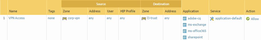
Click OK to save the interface configuration.If you created a separate zone for tunnel termination of VPN connections, create a security policy to enable traffic flow between the VPN zone and your trust zone.For example, the following policy rule enables traffic between the corp-vpn zone and the l3-trust zone.![]() Commit the configuration.
Commit the configuration.