Configure Interfaces and Zones
Table of Contents
Configure Interfaces and Zones
After you identify how you want to segment
your network and the zones you will need to create to achieve the
segmentation (as well as the interfaces to map to each zone), you
can begin configuring the interfaces and zones on the firewall. Configure
Interfaces on the firewall the to support the topology of
each part of the network you are connecting to. The following workflow
shows how to configure Layer 3 interfaces and assign them to zones.
For details on integrating the firewall using a different type of
interface deployments (for example as Virtual
Wire Interfaces or as Layer
2 Interfaces), see Networking.
The firewall comes preconfigured with a
default virtual wire interface between ports Ethernet 1/1 and Ethernet
1/2 (and a corresponding default security policy and virtual router).
If you do not plan to use the default virtual wire, you must manually
delete the configuration and commit the change before proceeding
to prevent it from interfering with other settings you define. For
instructions on how to delete the default virtual wire and its associated
security policy and zones, see Step 3 in Set
Up Network Access for External Services.
- Configure a default route to your Internet router.
- Select and then select the default link to open the Virtual Router dialog.Select the Static Routes tab and click Add. Enter a Name for the route and enter the route in the Destination field (for example, 0.0.0.0/0).Select the IP Address radio button in the Next Hop field and then enter the IP address and netmask for your Internet gateway (for example, 203.0.113.1).Click OK twice to save the virtual router configuration.Configure the external interface (the interface that connects to the Internet).
- Select and then select the interface you want to configure. In this example, we are configuring Ethernet1/16 as the external interface.Select the Interface Type. Although your choice here depends on interface topology, this example shows the steps for Layer3.On the Config tab, select New Zone from the Security Zone drop-down. In the Zone dialog, define a Name for new zone, for example Internet, and then click OK.In the Virtual Router drop-down, select default.To assign an IP address to the interface, select the IPv4 tab, click Add in the IP section, and enter the IP address and network mask to assign to the interface, for example 203.0.113.23/24.To enable you to ping the interface, select , expand the Management Profile drop-down, and select New Management Profile. Enter a Name for the profile, select Ping and then click OK.To save the interface configuration, click OK.Configure the interface that connects to your internal network.In this example, the interface connects to a network segment that uses private IP addresses. Because private IP addresses cannot be routed externally, you have to configure NAT.
- Select and select the interface you want to configure. In this example, we are configuring Ethernet1/15 as the internal interface our users connect to.Select Layer3 as the Interface Type.On the Config tab, expand the Security Zone drop-down and select New Zone. In the Zone dialog, define a Name for new zone, for example Users, and then click OK.Select the same Virtual Router you used previously, default in this example.To assign an IP address to the interface, select the IPv4 tab, click Add in the IP section, and enter the IP address and network mask to assign to the interface, for example 192.168.1.4/24.To enable you to ping the interface, select the management profile that you just created.To save the interface configuration, click OK.Configure the interface that connects to your data center applications.Although this basic security policy example configuration depicts using a single zone for all of your data center applications, you should define more granular zones to prevent unauthorized access to sensitive applications or data and eliminate the possibility of malware moving laterally within your data center.
- Select the interface you want to configure.Select Layer3 from the Interface Type drop-down. In this example, we are configuring Ethernet1/1 as the interface that provides access to your data center applications.On the Config tab, expand the Security Zone drop-down and select New Zone. In the Zone dialog, define a Name for new zone, for example Data Center Applications, and then click OK.Select the same Virtual Router you used previously, default in this example.To assign an IP address to the interface, select the IPv4 tab, click Add in the IP section, and enter the IP address and network mask to assign to the interface, for example 10.1.1.1/24.To enable you to ping the interface, select the management profile that you created.To save the interface configuration, click OK.(Optional) Create tags for each zone.Tags allow you to visually scan policy rules.
- Select and Add.Select a zone Name.Select a tag Color and click OK.
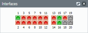
![]() Save the interface configuration.Click Commit.Cable the firewall.Attach straight through cables from the interfaces you configured to the corresponding switch or router on each network segment.Verify that the interfaces are active.Select Dashboard and verify that the interfaces you configured show as green in the Interfaces widget.
Save the interface configuration.Click Commit.Cable the firewall.Attach straight through cables from the interfaces you configured to the corresponding switch or router on each network segment.Verify that the interfaces are active.Select Dashboard and verify that the interfaces you configured show as green in the Interfaces widget.![]()