ION 1200-S-C-NA/ROW Front Panel
Table of Contents
ION 1200-S-C-NA/ROW Front Panel
Lets learn more about the ION 1200-S-C-NA/ROW Front Panel.
The front panel of the ION 1200-S-C-NA and ION 1200-S-C-ROW
are identical. The following image shows the front panel of the
ION 1200-S-C-NA/ROW and the table describes the front panel components.
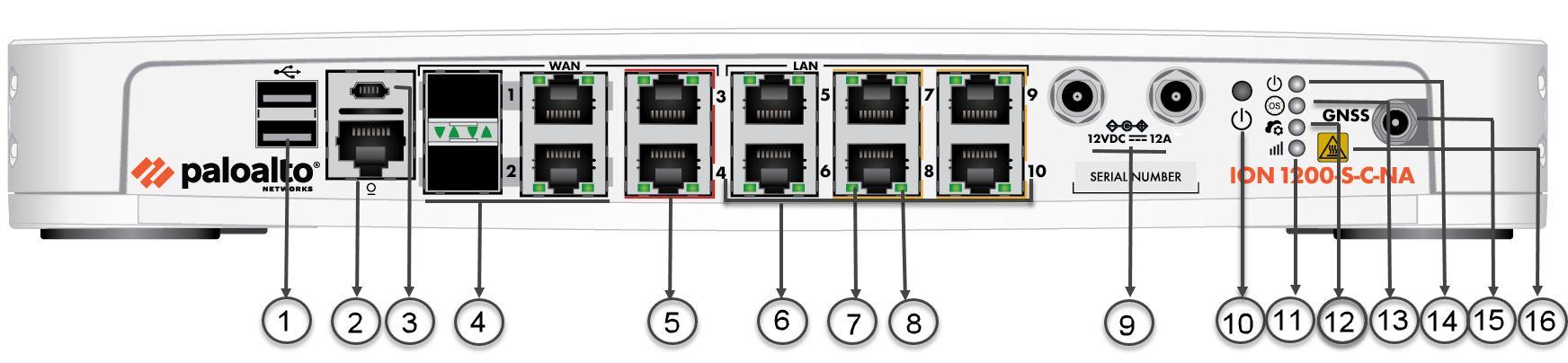
| Item | Component | Description |
|---|---|---|
| 1 | USB Port | USB 3.0 (reserved for future use). |
| 2 | Console Port | RJ-45 Serial console port. |
| 3 | Micro USB | Micro USB Type B Console connector. |
| 4 | SFP/RJ-45 Combo Ports | Ports 1 and 2 are SFP/RJ-45 combo ports. |
| 5 | ByPass Pair | Ports 3 and 4 are bypass pairs. ByPass ports are indicated with an orange bar above and below the ports. |
| 6 | Ethernet Ports | Ports 1-10 are access ports. Ports 7-10 are PoE ports indicated with a yellow bar above and below the ports. |
| 7 | Link Speed LED | On ethernet ports 1-10, the left LED indicates the link speed. |
| 8 | Activity LED | On ethernet ports 1-10, the right LED indicates the activity on the port. |
| 9 | Power | Power Input. |
| 10 | Restart button | Restart button. |
| 12 | Controller LED | Controller LED; the LED turns green on successful connection with the Prisma SD-WAN controller. |
| 13 | OS LED | Operating System status LED. |
| 14 | Power LED | Power LED; the LED turns green when powered on. |
| 15 | Antenna Connector | Antenna SMA (F) Connectors. ION 1200-S-C-NA/ROW has three antenna connectors—Main (TX/RX1), Aux (RX2), GNSS. |
| 16 | Heat Label | Heat label on the device. |