PA-3200 Series Front Panel
Table of Contents
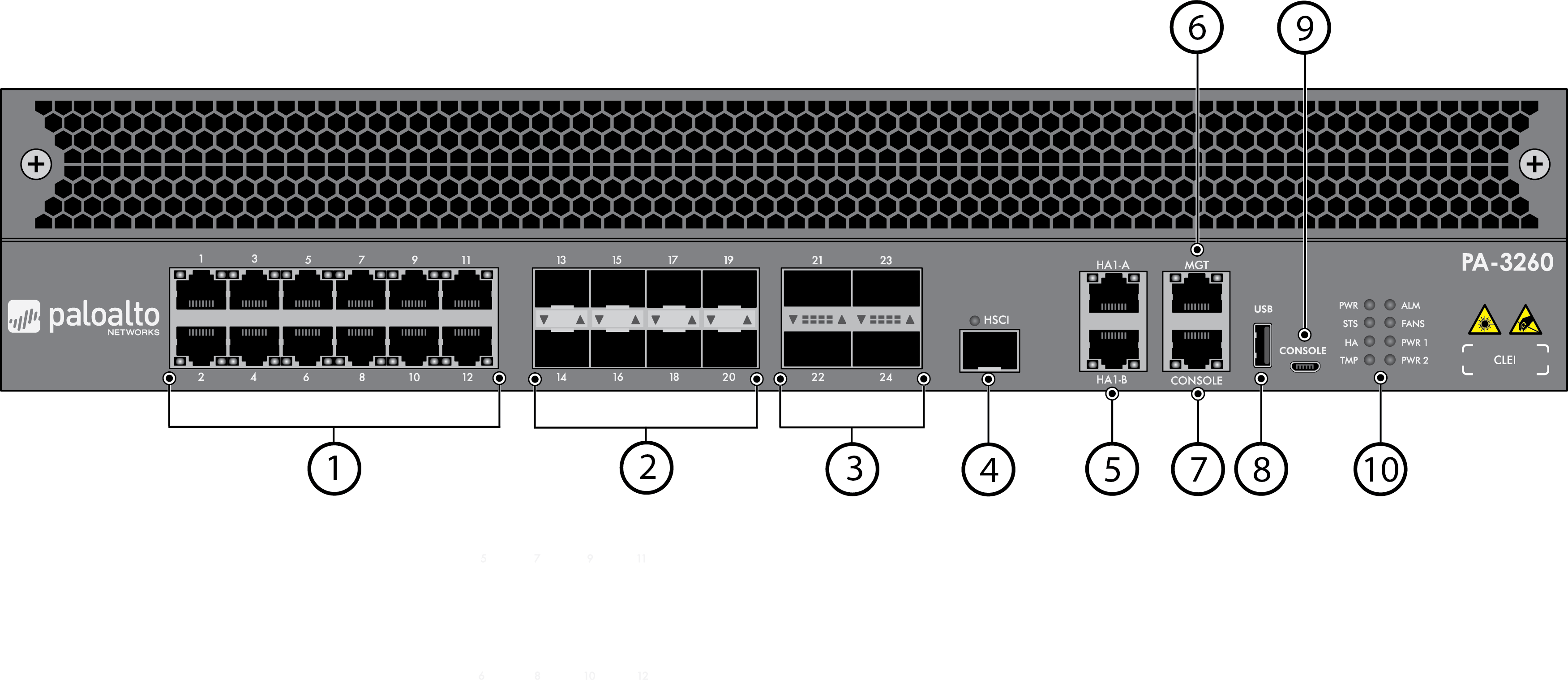
PA-3200 Series Front Panel
Learn about the PA-3200 Series firewall front-panel components.
The following image shows the front panel of the PA-3200
Series firewall and the table describes each front panel component.
The only differences between the PA-3220, PA-3250, and PA-3260 (shown)
front panels are the model name and the Ethernet ports, as described
in the table.
Item | Component | Description |
|---|---|---|
1 | Ethernet ports 1 through 12 | Twelve RJ-45 10Mbps/100Mpbs/1Gbps ports for
network traffic. The link speed and link duplex are auto-negotiate
only. |
2 | SFP ports 13 through 20 | These ports vary depending on your firewall model:
|
3 | QSFP+ ports 21 through 24 | (PA-3260 only) Four QSFP+ (40Gbps)
ports as defined by the IEEE 802.3ba standard. |
4 | HSCI port | One SFP+ (10Gbps) port (supports only an SFP+
transceiver or passive SFP+ cable). Use this port to connect
two PA-3200 Series firewalls in a high availability (HA) configuration
as follows:
The
HSCI ports must be connected directly between the two firewalls
in the HA configuration (without a switch or router between them).
When directly connecting the HSCI ports between two PA-3200 Series
firewalls that are physically located near each other, Palo Alto
Networks recommends that you use a passive SFP+ cable. For
installations where the two firewalls are not near each other and
you cannot use a passive SFP+ cable, use a standard SFP+ transceiver
and the appropriate cable length. |
5 | HA1-A and HA1-B ports | Two RJ-45 10Mbps/100Mbps/1000Mbps ports for
high availability (HA) control. To support high availability
over a long distance, you must use an external device such as a
dry VLAN. If the firewall dataplane restarts due
to a failure or manual restart, the HA1-B link will also restart.
If this occurs and the HA1-A link is not connected and configured,
then a split brain condition occurs. Therefore, we recommend that
you connect and configure the HA1-A ports and the HA1-B ports to provide
redundancy and to avoid split brain issues. |
6 | MGT port | Use this Ethernet 10Mbps/100Mbps/1000Mbps port
to access the management web interface and perform administrative
tasks. The firewall also uses this port for management services,
such as retrieving licenses and updating threat and application signatures. |
| 7 | CONSOLE port (RJ-45) | Use this port to connect a management computer
to the firewall using a 9-pin serial-to-RJ-45 cable and terminal
emulation software. The console connection provides access
to firewall boot messages, the Maintenance Recovery Tool (MRT),
and the command line interface (CLI). If your management
computer does not have a serial port, use a USB-to-serial converter. Use
the following settings to configure your terminal emulation software
to connect to the console port:
|
| 8 | USB port | A USB port that accepts a USB flash drive
with a bootstrap bundle (PAN-OS configuration). Bootstrapping
speeds up the process of configuring and licensing the firewall
to make it operational on the network with or without internet access. |
| 9 | CONSOLE port (Micro USB) | Use this port to connect a management computer
to the firewall using a standard Type-A USB-to-micro USB cable. The
console connection provides access to firewall boot messages, the
Maintenance Recovery Tool (MRT), and the command line interface (CLI). Refer
to the Micro USB Console Port page for more information
and to download the Windows driver or to learn how to connect from
a Mac or Linux computer. |
10 | LED status indicators | Eight LEDs that indicate the status of the firewall
hardware components (see Interpret
the PA-3200 Series Status LEDs). |