Network Security
Site-to-Site VPN with Static Routing
Table of Contents
Expand All
|
Collapse All
Network Security Docs
Site-to-Site VPN with Static Routing
| Where Can I Use This? | What Do I Need? |
|---|---|
| No license required |
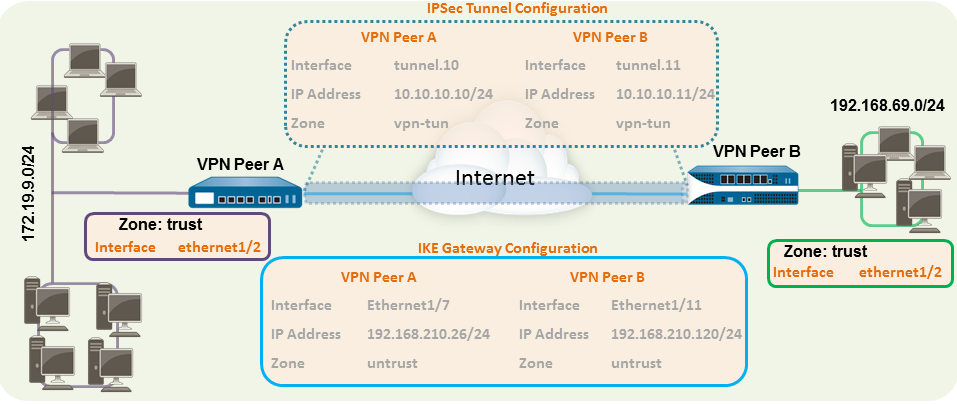
The following example shows a VPN connection between two sites that use static routes. Without
dynamic routing, the tunnel interfaces on VPN Peer A and VPN Peer B don’t require an
IP address because the firewall automatically uses the tunnel interface as the next
hop for routing traffic across the sites. However, to enable tunnel monitoring, a
static IP address has been assigned to each tunnel interface.

- Configure a Layer 3 interface.This interface is used for the IKE phase-1 tunnel.
- Select NetworkInterfacesEthernet and then select the interface you want to configure for VPN.Select Layer3 from the Interface Type.On the Config tab, select the Security Zone to which the interface belongs:
- The interface must be accessible from a zone outside of your trust network. Consider creating a dedicated VPN zone for visibility and control over your VPN traffic.
- If you haven’t yet created the zone, select New Zone from the Security Zone, define a Name for the new zone, and then click OK.
Select the Virtual Router to use.To assign an IP address to the interface, select the IPv4 tab, click Add in the IP section, and enter the IP address and network mask to assign to the interface, for example 192.168.210.26/24.To save the interface configuration, click OK.In this example, the configuration for VPN Peer A is:- Interface—ethernet1/7
- Security Zone—untrust
- Virtual Router—default
- IPv4—192.168.210.26/24
The configuration for VPN Peer B is:- Interface—ethernet1/11
- Security Zone—untrust
- Virtual Router—default
- IPv4—192.168.210.120/24
Create a tunnel interface and attach it to a virtual router and security zone.- Select NetworkInterfacesTunnel and click Add.In the Interface Name field, specify a numeric suffix, such as .1.On the Config tab, expand the Security Zone to define the zone as follows:
- To use your trust zone as the termination point for the tunnel, select the zone.
- (Recommended) To create a separate zone for VPN tunnel termination, click New Zone. In the Zone dialog, define a Name for a new zone (for example vpn-tun), and then click OK.
Select the Virtual Router.(Optional) Assign an IP address to the tunnel interface, select the IPv4 or IPv6 tab, click Add in the IP section, and enter the IP address and network mask to assign to the interface.With static routes, the tunnel interface doesn’t require an IP address. For traffic that is destined to a specified subnet/IP address, the tunnel interface will automatically become the next hop. Consider adding an IP address if you want to enable tunnel monitoring.To save the interface configuration, click OK.In this example, the configuration for VPN Peer A is:- Interface—tunnel.10
- Security Zone—vpn_tun
- Virtual Router—default
- IPv4—172.19.9.2/24
The configuration for VPN Peer B is:- Interface—tunnel.11
- Security Zone—vpn_tun
- Virtual Router—default
- IPv4—192.168.69.2/24
Configure a static route, on the virtual router, to the destination subnet.- Select NetworkVirtual Router and click the router you defined in the prior step.Select Static Route, click Add, and enter a new route to access the subnet that is at the other end of the tunnel.In this example, the configuration for VPN Peer A is:
- Destination—192.168.69.0/24
- Interface—tunnel.10
The configuration for VPN Peer B is:- Destination—172.19.9.0/24
- Interface—tunnel.11
Set up the crypto profiles (IKE Crypto profile for phase 1 and IPSec Crypto profile for phase 2).Complete this task on both peers and make sure to set identical values.- Select NetworkNetwork ProfilesIKE Crypto. In this example, we use the default profile.Select NetworkNetwork ProfilesIPSec Crypto. In this example, we use the default profile.Set up the IKE Gateway.
- Select NetworkNetwork ProfilesIKE Gateway.Click Add and configure the options in the General tab.In this example, the configuration for VPN Peer A is:
- Interface—ethernet1/7
- Local IP address—192.168.210.26/24
- Peer IP type/address—static/192.168.210.120
- Preshared keys—enter a value
- Local identification—None; this means that the local IP address will be used as the local identification value.
- The configuration for VPN Peer B is:
- Interface—ethernet1/11
- Local IP address—192.168.210.120/24
- Peer IP type/address—static/192.168.210.26
- Preshared keys—enter same value as on Peer A
- Local identification—None
Select Advanced Phase 1 Options and select the IKE Crypto profile you created earlier to use for IKE phase 1.Set up the IPSec Tunnel.- Select NetworkIPSec Tunnels.Click Add and configure the options in the General tab.In this example, the configuration for VPN Peer A is:
- Tunnel Interface—tunnel.10
- Type—Auto Key
- IKE Gateway—Select the IKE Gateway defined above.
- IPSec Crypto Profile—Select the IPSec Crypto profile defined in step 4.
The configuration for VPN Peer B is:- Tunnel Interface—tunnel.11
- Type—Auto Key
- IKE Gateway—Select the IKE Gateway defined above.
- IPSec Crypto Profile—Select the IPSec crypto defined in step 4.
(Optional) Select Show Advanced Options, select Tunnel Monitor, and specify a Destination IP address to ping for verifying connectivity. Typically, the tunnel interface IP address for the VPN Peer is used.(Optional) To define the action on failure to establish connectivity, see Define a Tunnel Monitoring Profile.Create policy rules to allow traffic between the sites (subnets).- Select PoliciesSecurity.Create rules to allow traffic between the untrust and the vpn-tun zone and the vpn-tun and the untrust zone for traffic originating from specified source and destination IP addresses.Commit any pending configuration changes.Click Commit.
