Prisma Access
Configure Prisma Access Colo-Connect
Table of Contents
Expand All
|
Collapse All
Prisma Access Docs
-
- 6.1 Preferred and Innovation
- 6.0 Preferred and Innovation
- 5.2 Preferred and Innovation
- 5.1 Preferred and Innovation
- 5.0 Preferred and Innovation
- 4.2 Preferred
- 4.1 Preferred
- 4.0 Preferred
- 3.2 Preferred and Innovation
- 3.1 Preferred and Innovation
- 3.0 Preferred and Innovation
- 2.2 Preferred
-
-
- 4.0 & Later
- Prisma Access China
-
-
Configure Prisma Access Colo-Connect
Configure a Colo-Connect deployment in Prisma Access.
| Where Can I Use This? | What Do I Need? |
|---|---|
|
|
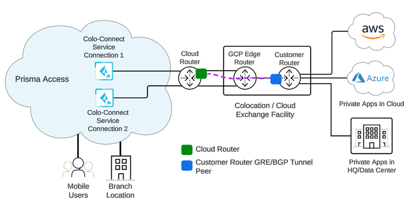
Prisma Access Colo-Connect consists of the following components:
- Colo—The colocation facility that provides rack-space, power and connectivity to host networking, private and public cloud infrastructure, such as Equinix.
- Dedicated Interconnect—The dedicated Layer 2 or Layer 3 physical connection between your router and a GCP edge router in a given GCP compute region. A dedicated Interconnect provides a direct physical connection between your on-premises network and the Google network.Interconnects are called Links in the Prisma Access UI.
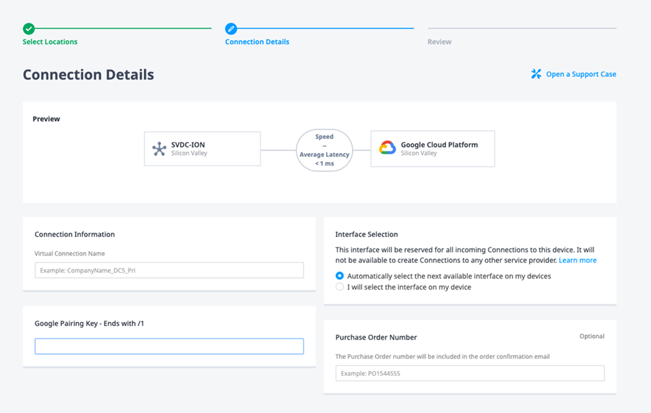
- GCP VLAN Attachment—The logical Layer 2 connection over the link that separates traffic from any other logical connections sharing the same link.VLAN attachments are called Connections in the Prisma Access UI.
- Partner Interconnect—The connection between a service provider owned router and a GCP edge router in a given GCP compute region. A partner Interconnect provides both Layer 2 and Layer 3 connectivity between your on-premises and VPC networks through a supported service provider. Colo-Connect uses the interconnect to bring up the underlay BGP routing.Colo-Connect supports both Dedicated and Partner interconnects.
- Colo (Customer) Router—The routing device in the Colo facility that establishes eBGP with the GCP cloud router over the interconnect in the Colo facility, as well as eBGP with Colo-Connect service connection over the GRE tunnel. It is a customer router for a dedicated interconnect, or if the service provider has Layer 2 connectivity with GCP over the partner interconnect. The service provider owns the Colo router when it has Layer 3 connectivity with the GCP cloud-router.
- GCP Edge Router—GCP's network edge equipment to provide physical connectivity between GCP and the customer/partner network via the Colo.
- Cloud Router—The GCP software construct in the cloud that establishes BGP sessions with the networking device (for example, router or Layer 3 firewall) in the Colo and routes traffic between Prisma Access and your network. You are not required to configure this component; it is automatically done by Prisma Access.
To configure Colo-Connect, you must first gather information about your existing
network environment and make sure that you have all required network components in
place. Ensure you have all prerequisites; then, deploy Colo-Connect in your
organization's network using either a partner or a dedicated interconnect.
Configure Prisma Access Colo-Connect (Strata Cloud Manager)
Configure a Colo-Connect deployment in Prisma Access.
Configure Prisma Access Colo-Connect—Deployments Using Partner Interconnects
To configure Prisma Access Colo-Connect using a partner interconnect, complete these
steps.
- Create subnets for your Colo-Connect connections.You use the subnets you create here in the connections and service connections that you create in later steps.
- From Strata Cloud Manager, go to ConfigurationColo Connect.Add Prefix and add a Colo-Connect subnet and a Prisma Access location for it.See the list of supported Colo-Connect locations here. Enter a minimum subnet of /28.(Optional) If you plan on creating Colo-Connect instances for more than one location, add more subnets on a per-location basis.You can configure one subnet per location.
![]() Commit and Push your configuration changes, making sure that Colo-Connect is selected in the Push Scope.Wait at least three minutes to wait for the subnet configuration changes to populate.Add a new Colo-Connect link (also known as the interconnect).
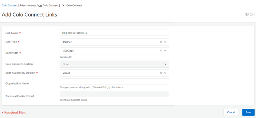
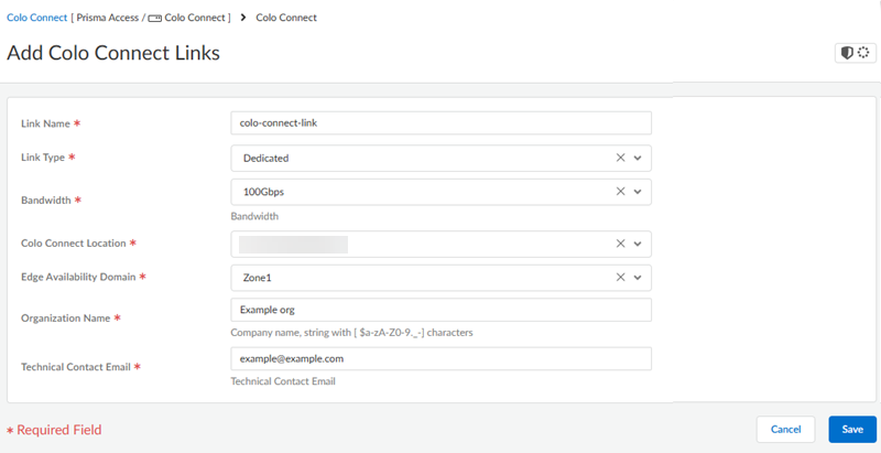
Commit and Push your configuration changes, making sure that Colo-Connect is selected in the Push Scope.Wait at least three minutes to wait for the subnet configuration changes to populate.Add a new Colo-Connect link (also known as the interconnect).- Go to ConfigurationColo-Connect and Add Link.Specify the Colo-Connect link parameters.
- Give the link a unique Link Name.
- Select Partner interconnect as the Link Type
- Select a Bandwidth for the connection.You can select between 10 Gbps, 20 Gbps, 50 Gbps, or 100 Gbps.Skip the Colo Connect Location; this field is populated as None for Partner interconnects.
- Select either Zone1 or Zone2 for the Edge Availability Domain. Take this value from the GCP zone used for your edge availability domain.
- (Optional) Enter the Organization Name to use for this link.
- Enter the Email to use for this link. Any email address is acceptable.
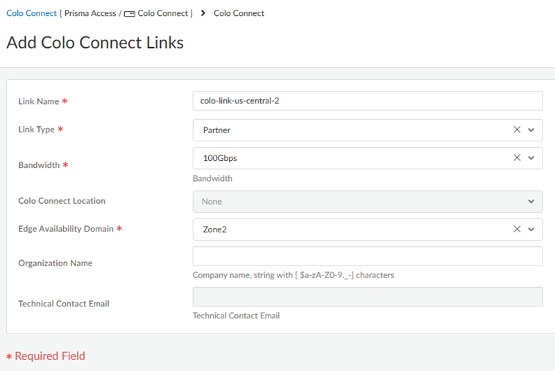
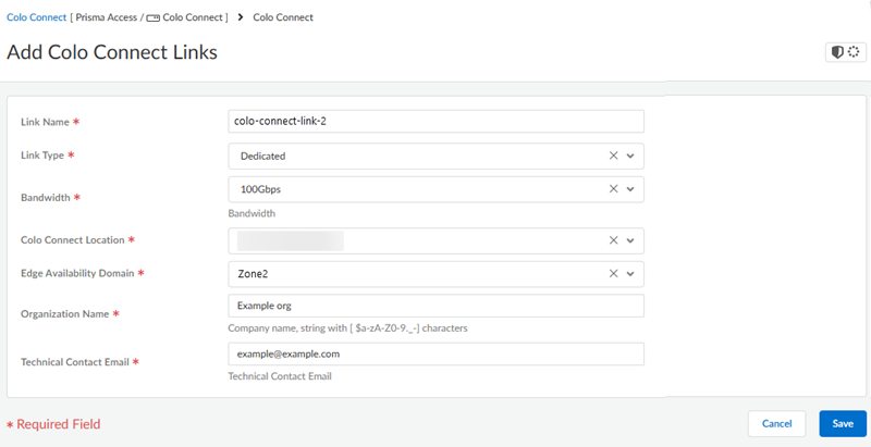
![]() Add a second link with a different Edge Availability Domain.
Add a second link with a different Edge Availability Domain.![]() Create the connections (also known as the VLAN attachments) for Colo-Connect.
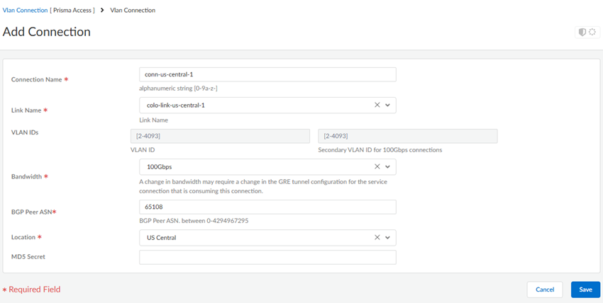
Create the connections (also known as the VLAN attachments) for Colo-Connect.- Go to ConfigurationColo-Connect and Add Connection.Configure the connection settings.
- Enter a unique Connection Name.
- Select a Link Name from the links you
configured in a previous step.You do not need to enter a VLAN ID; it's not configurable for VLANs created on partner interconnects.
- Select a Bandwidth for the connection.You can select between 1 Gbps, 2 Gbps, 5 Gbps, 10 Gbps, 20 Gbps, 50 Gbps, or 100 Gbps.If you configure multiple connections for an interconnect, make sure that the total bandwidth of the connections does not exceed the bandwidth of the interconnect. For example, given a partner interconnect of 100 Gbps, you can configure 10 connections of 10 Gbps each, but don't exceed 100 Gbps in total for all connections.If your deployment requires more than 16 Colo-Connect instances, reach out to your Palo Alto Networks account team, who will open an SRE case to accommodate the request.
- Enter a BGP Peer ASN. Enter the Autonomous System (AS) number for the customer on-premises router in the Colo. The range is between 1 and 4294967295.
- Select the Location from the
connection names you created in a previous step. You must have already added a subnet for any location you specify.
- (Optional) Enter the BGP MD5 Secret.
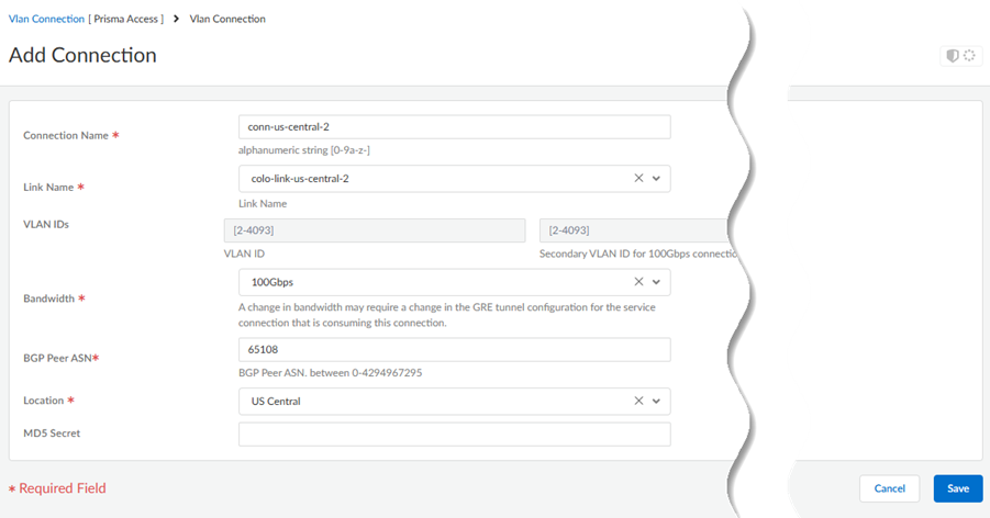
![]() Create a second connection.Both connections must be in the same region and one connection each must be in a separate zone. You use these connections in service connections you create in a later step.
Create a second connection.Both connections must be in the same region and one connection each must be in a separate zone. You use these connections in service connections you create in a later step.![]() Push Config.After the push completes, view the Pairing Key under Connections.
Push Config.After the push completes, view the Pairing Key under Connections.![]() Copy the Pairing Key or keys and complete your partner interconnect configuration.If you specify 100 Gbps of bandwidth in a connection, you receive four pairing keys, two for each 50 Gbps VLAN attachment.You use this pairing key or keys when you set up the partner interconnect in the Colo.When you first onboard a new connection, the Status in the Connections area shows a Status of PENDING_PARTNER and a BGP Status of DOWN. To bring the connection status to ACTIVE, retrieve the pairing key and input in the connection at the Colo.
Copy the Pairing Key or keys and complete your partner interconnect configuration.If you specify 100 Gbps of bandwidth in a connection, you receive four pairing keys, two for each 50 Gbps VLAN attachment.You use this pairing key or keys when you set up the partner interconnect in the Colo.When you first onboard a new connection, the Status in the Connections area shows a Status of PENDING_PARTNER and a BGP Status of DOWN. To bring the connection status to ACTIVE, retrieve the pairing key and input in the connection at the Colo.- Create a new VLAN connection in the Colo.
![]() Paste the Pairing Key or keys in the Colo VLAN.GCP detects when the pairing key is consumed, brings the VLAN status to ACTIVE, and generates the BGP IP address for you to configure on your on-premises router in the Colo. Prisma Access uses these IP addresses to initiate eBGP adjacency over each associated VLAN between Colo router and GCP cloud router.Configure eBGP routing on the Customer (Colo) router for the Colo-Connect connection.You need to set up BGP routing to ensure connectivity between the customer router and the cloud router.Set up the service connections to use with Colo-Connect.Push Config.Check the status of the Colo-Connect connections.
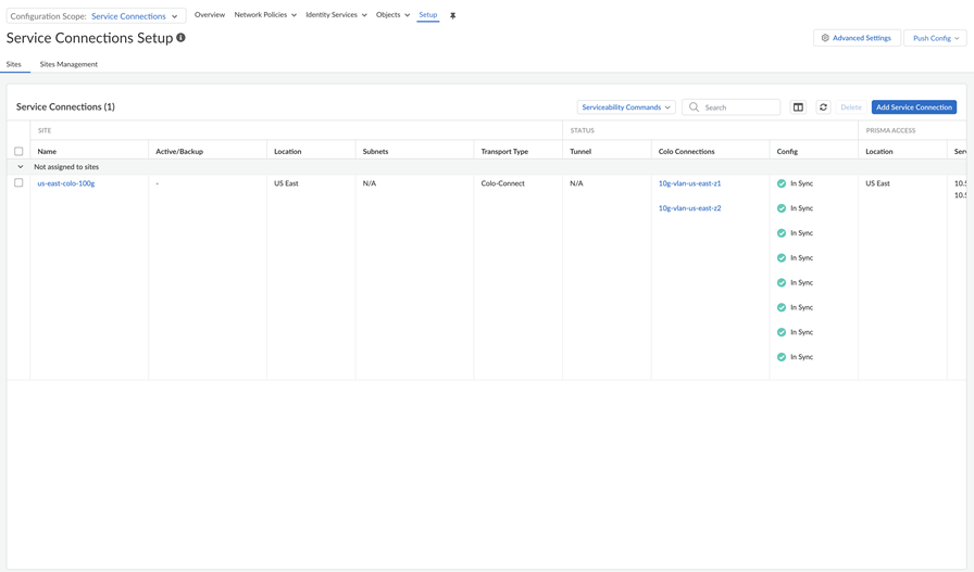
Paste the Pairing Key or keys in the Colo VLAN.GCP detects when the pairing key is consumed, brings the VLAN status to ACTIVE, and generates the BGP IP address for you to configure on your on-premises router in the Colo. Prisma Access uses these IP addresses to initiate eBGP adjacency over each associated VLAN between Colo router and GCP cloud router.Configure eBGP routing on the Customer (Colo) router for the Colo-Connect connection.You need to set up BGP routing to ensure connectivity between the customer router and the cloud router.Set up the service connections to use with Colo-Connect.Push Config.Check the status of the Colo-Connect connections.- To check the status of a service connection used by a Colo-Connect connection, go to ConfigurationNGFW and Prisma AccessConfiguration ScopePrisma AccessService Connections.
![]() (Optional) If tunnels are used, check the status of the tunnels in the Tunnel area.Check the connection details, including the Pairing Key or keys, of the Colo-Connect connections by going to ConfigurationColo Connect.
(Optional) If tunnels are used, check the status of the tunnels in the Tunnel area.Check the connection details, including the Pairing Key or keys, of the Colo-Connect connections by going to ConfigurationColo Connect.Configure Prisma Access Colo-Connect—Deployments Using Dedicated Interconnects
To configure Prisma Access Colo-Connect using a dedicated interconnect, complete these steps. - Create subnets for your Colo-Connect connections.You use the subnets you create here in the connections and service connections that you create in later steps.
- From Strata Cloud Manager, go to ConfigurationColo-Connect and click the gear icon to edit the settings.Add Prefix and add a Colo-Connect subnet a Prisma Access location for it.See the list of supported colo-connect locations here. Enter a minimum subnet of /28.(Optional) If you plan on creating Colo-Connect instances for more than one location, Add more subnets on a per-location basis.You can configure only one subnet per location.Add a new Colo-Connect link (also known as the interconnect).
- Go to ConfigurationColo-Connect and Add Link.Give the link a unique Link Name.Select a Dedicated interconnect as the Link Type.Specify the remaining Colo-Connect link parameters.
- Select a Bandwidth for the connection.You can select between 10 Gbps, 20 Gbps,50 Gbps, or 100 Gbps.You can't change the bandwidth of a dedicated interconnect link after you specify it and commit and push your changes.
- Select a Colo-Connect Location from
the drop-down list.Make sure that you select the same location that you used for the dedicated interconnect.
- Select either Zone1 or Zone2 for the Edge Availability Domain. Take this value from the GCP zone used for your edge availability domain.
- Enter the Organization Name to use for this link.
- Enter the Email where you want to
receive the LOA-CFA details from the cloud provider.
- GCP uses this email to send the Letter of Authorization and Connecting Facility Assignment (LOA-CFA). Be sure that the LOA-CFA is sent to your Colo provider, so they can begin to install your connections.
![]()
Add a second link with a different Edge Availability Domain.![]() After the dedicated connection is created, the Colo facility tests your connections and informs you that they have been tested and are ready to use.No Prisma Access configuration is required for this step. Don't create the Colo-Connect connections in Prisma Access until the Colo facility lets you know that they have been tested.Create the connections (also known as the VLAN attachments) for Colo-Connect.
After the dedicated connection is created, the Colo facility tests your connections and informs you that they have been tested and are ready to use.No Prisma Access configuration is required for this step. Don't create the Colo-Connect connections in Prisma Access until the Colo facility lets you know that they have been tested.Create the connections (also known as the VLAN attachments) for Colo-Connect.- Make sure that the dedicated link status is Active by going to ConfigurationColo-ConnectColo Connect Links.Until the Dedicated link status is Active, you can't create Colo-Connect connections.
![]() Go to ConfigurationColo-Connect and Add Connection.Configure the connection settings.
Go to ConfigurationColo-Connect and Add Connection.Configure the connection settings.- Enter a unique Connection Name.
- Select a Link Name from the links you configured in a previous step.
- (Optional) Enter a VLAN ID
for the connection. VLAN IDs are generated by the interconnect vendor (GCP) if you don't manually enter a value.
- Select a Bandwidth for the connection.You can select between 1 Gbps, 2 Gbps, 5 Gbps, 10 Gbps, 20 Gbps, 50 Gbps, or 100 Gbps.If you configure multiple connections for an interconnect, make sure that the total bandwidth of the connections does not exceed the bandwidth of the interconnect. For example, given a partner interconnect of 100 Gbps, you can configure 10 connections of 10 Gbps each, but don't exceed 100 Gbps in total for all connections.If your deployment requires more than 16 Colo-Connect instances, reach out to your Palo Alto Networks account team, who will open an SRE case to accommodate the request.
- Enter a BGP Peer ASN. Enter the Autonomous System (AS) number for the customer on-premises router in the Colo. The range is between 1 and 4294967295.
- Select the Location from the
connection names you created in a previous step. You must have already added a subnet for any location you specify.
- (Optional) Enter the BGP MD5 Secret.
![]() Create a second connection.Both connections must be in the same region and one connection each must be in a separate zone. You use these connections in service connections you create in a later step.Push Config.Configure eBGP routing on the customer router.You need to set up BGP peering to ensure connectivity between the customer router.Set up the service connections to use with Colo-Connect.Commit and Push your configuration changes, making sure that Colo-Connect is selected in the Push Scope.Check the status of Colo-Connect connections and service connections.
Create a second connection.Both connections must be in the same region and one connection each must be in a separate zone. You use these connections in service connections you create in a later step.Push Config.Configure eBGP routing on the customer router.You need to set up BGP peering to ensure connectivity between the customer router.Set up the service connections to use with Colo-Connect.Commit and Push your configuration changes, making sure that Colo-Connect is selected in the Push Scope.Check the status of Colo-Connect connections and service connections.- To check the status of a service connection used by a Colo-Connect connection, go to ConfigurationNGFW and Prisma AccessConfiguration ScopePrisma AccessService Connections.
![]() (Optional) If tunnels are used, check the status of the tunnels in the Tunnel area.Check the network details of the Colo-Connect connections by going to ConfigurationColo-ConnectConnections.For dedicated links, the Pairing Key displays as N/A.
(Optional) If tunnels are used, check the status of the tunnels in the Tunnel area.Check the network details of the Colo-Connect connections by going to ConfigurationColo-ConnectConnections.For dedicated links, the Pairing Key displays as N/A.![]()
Configure VLAN eBGP Routing on the Customer Router
GCP creates IP addresses for the customer (Colo) router and the cloud router during these stages of your deployment:- For partner interconnects, GCP creates the IP addresses after the pairing key is consumed by your Colo (for example, Equinix).
- For dedicated interconnects, GCP creates the IP addresses after you onboard your Colo-Connect connections (VLAN attachments) and commit and push your changes.
To ensure correct routing, you must:- Configure the Colo router IP address (the Colo CPE IP in Prisma Access) as the local eBGP IP address
- Configure the cloud router IP address (Cloud Router IP) as the eBGP peer address on your Colo router.
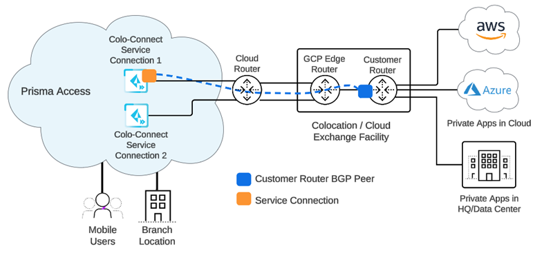
When complete, eBGP is configured for the connection (VLAN attachment) between the Colo router and the cloud router.![]() Creating this routing is the first step in setting up BGP routing. You complete the BGP routing when you set up tunnels during service connection configuration.These examples use Palo Alto Networks next-generation firewalls as the router; third-party CPE routers (for example, Cisco routers) are also supported.Use the following steps to configure routing between the Colo and the cloud router.
Creating this routing is the first step in setting up BGP routing. You complete the BGP routing when you set up tunnels during service connection configuration.These examples use Palo Alto Networks next-generation firewalls as the router; third-party CPE routers (for example, Cisco routers) are also supported.Use the following steps to configure routing between the Colo and the cloud router.- From Strata Cloud Manager, create the subnets, links, and connections and Push Config.Use the workflow specific to your interconnect type (either Partner or Dedicated) For Partner interconnects, be sure that you pasted the Pairing Key into the Colo VLAN.Go to ConfigurationColo-ConnectConnections.Make a note of the following connection elements after you've onboarded Colo-Connect:
- Cloud Router IP
- Cloud Router BGP ASN
- Colo CPE IP
The Cloud Router IP and Colo-CPE IP are link-local addresses. The following examples use:- 169.254.14.49/29 as the Cloud Router IP
- 169.254.14.50/29 as the Colo CPE IP
- 65108 as the Colo BGP ASN
![]() (Deployments that use GRE tunnels only) Determine the IP addresses you will use for the local tunnel IP addresses when you set up the Colo-Connect service connections.Log in to the Colo router.The following configuration screenshots use a Palo Alto Networks Next-Generation Firewall as the Colo router.Add a VLAN interface, specifying the Colo CPE IP address as the IP address.If you're using a next-generation firewall as the Colo router, go to NetworkInterfacesVLANs and Add the VLAN interface.
(Deployments that use GRE tunnels only) Determine the IP addresses you will use for the local tunnel IP addresses when you set up the Colo-Connect service connections.Log in to the Colo router.The following configuration screenshots use a Palo Alto Networks Next-Generation Firewall as the Colo router.Add a VLAN interface, specifying the Colo CPE IP address as the IP address.If you're using a next-generation firewall as the Colo router, go to NetworkInterfacesVLANs and Add the VLAN interface.![]() Configure the Colo router IP address (Colo CPE IP) as the local eBGP IP address and Configure the cloud router IP address (Cloud Router IP) as the eBGP peer address on your Colo router.If you're using a next-generation firewall as the Colo router, go to NetworkVirtual Routers, Add a virtual router, go to BGPPeer Group, and enter the Colo CPE IP as the Local Address and the Cloud Router IP as the Peer Address.
Configure the Colo router IP address (Colo CPE IP) as the local eBGP IP address and Configure the cloud router IP address (Cloud Router IP) as the eBGP peer address on your Colo router.If you're using a next-generation firewall as the Colo router, go to NetworkVirtual Routers, Add a virtual router, go to BGPPeer Group, and enter the Colo CPE IP as the Local Address and the Cloud Router IP as the Peer Address.![]() Configure the Cloud Router BGP ASN as the eBGP AS Number.Create the Colo-Connect service connections.
Configure the Cloud Router BGP ASN as the eBGP AS Number.Create the Colo-Connect service connections.Create Colo-Connect Service Connections
Colo-Connect uses service connections, but they differ from standard Prisma Access Service Connections. - Make sure that Prisma Access withdraws static routes by going to Configuration NGFW and Prisma AccessConfiguration ScopePrisma AccessService ConnectionsAdvanced Settings, and selecting Withdraw Static Routes if Service Connection or Remote Network IPSec tunnel is down.Selecting this choice ensures that, if the tunnel is down, the static route used by the tunnel is withdrawn.
![]() Go to ConfigurationColo-ConnectConnections and make sure that the connections are in an Active state by checking their Status.Until the Status of the connection is Active, you can't configure service connections.
Go to ConfigurationColo-ConnectConnections and make sure that the connections are in an Active state by checking their Status.Until the Status of the connection is Active, you can't configure service connections.![]() Refresh your browser so that the Colo-Connect configuration is provisioned in the service connections area.Go to ConfigurationNGFW and Prisma AccessConfiguration ScopePrisma AccessService Connection.Add Service Connection, give it a unique Name, and select a Transport Type of Colo-Connect.Make sure that the name you enter is 31 characters long or less; entering a name 32 characters or longer causes the tunnel to be mapped incorrectly in the Prisma Access infrastructure.Select two connections to use with the service connections (Connection 1 and Connection 2).These connections must be in two different zones.
Refresh your browser so that the Colo-Connect configuration is provisioned in the service connections area.Go to ConfigurationNGFW and Prisma AccessConfiguration ScopePrisma AccessService Connection.Add Service Connection, give it a unique Name, and select a Transport Type of Colo-Connect.Make sure that the name you enter is 31 characters long or less; entering a name 32 characters or longer causes the tunnel to be mapped incorrectly in the Prisma Access infrastructure.Select two connections to use with the service connections (Connection 1 and Connection 2).These connections must be in two different zones.![]() Select Active or Backup for Connection 1 and Connection 2Use these guidelines when setting up service connections:
Select Active or Backup for Connection 1 and Connection 2Use these guidelines when setting up service connections:- You can configure connections in these modes:
- Active/Active
- Active/Backup
- Backup/Active
Configuring both connections in Backup/Backup mode is invalid and not supported. - The bandwidth of the connections must be the same for all modes.
- The connections must be in different zones.
- The maximum bandwidth you can specify for a service connection is 100 Gbps. If you specify a Bandwidth of 100 Gbps for a connection, you can't use that connection in a Active/Active configuration (it must be set as Active/Backup).
- Don't mix dedicated and partner interconnects in the same service
connection, and make sure that the interconnects use different
zones. This table shows the allowed and disallowed configurations
for service connections, assuming that zones, locations, bandwidth,
and roles follow the service connection guidelines and
requirements:
Connection 1 Belongs To Connection 2 Belongs To Valid Colo-Connect Service Connection Configuration? Partner Connect 1 Partner Connect 2 Yes Dedicated Connect 1 Dedicated Connect 2 Yes Partner Connect 1 Partner Connect 1 No Dedicated Connect 1 Dedicated Connect 1 No Partner Connect Dedicated Connect No
(Optional and for hot potato routing deployments only) Select a service connection to use as the preferred backup, which is the Backup SC, in the hot potato routing configuration.You can only select a service connection that has been configured as a Colo-Connect service connection. Prisma Access uses the Backup SC you select as the preferred service connection in the event of a connection failure. Selecting a backup service connection can prevent asymmetric routing issues if you have created more than two service connections.(Optional) Enable Source NAT for Mobile Users—GlobalProtect IP pool addresses, IP addresses in the Infrastructure subnet, or both.You can specify a subnet at one or more service connections that are used to NAT traffic between Prisma Access GlobalProtect mobile users and private applications and resources at a data center.- Enable Data Traffic Source NAT—Performs NAT on Mobile User IP address pool addresses so that they are not advertised to the data center, and only the subnets you specify at the service connections are advertised and routed in the data center.
- Enable Infrastructure Traffic Source NAT—Performs NAT on addresses from the Infrastructure subnet so that they are not advertised to the data center, and only those subnets you specify at the service connections are advertised and routed in the data center.
- IP Pool—Specify the IP address pool used to perform NAT on the mobile user IP address pool, Infrastructure subnet, or both. Use a private IP (RFC 1918) subnet or a suitable subnet that’s routable in your routing domain, and does not overlap with the Mobile Users—GlobalProtect IP address pool or the Infrastructure subnet. Enter a subnet between /25 and /32.
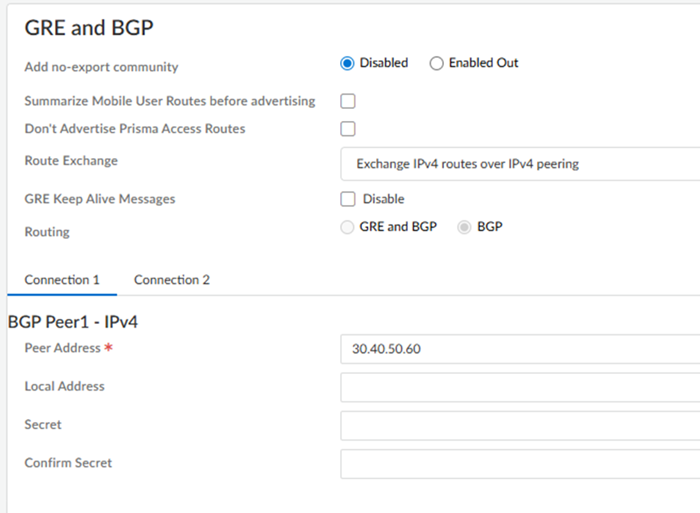
In the GRE and BGP area, configure the GRE tunnel (if required) and BGP settings for the service connection.Connections that have 50 Gbps or more don't require GRE tunnel configuration.- (Optional) Select from the following choices:
- To add a no-export community for Corporate Access Nodes (Service Connections) to the outbound prefixes from the eBGP peers at the customer premises equipment (CPE), set Add no-export community to Enabled Out. This capability is Disabled by default.Don't use this capability in hot potato routing mode.
- To reduce the number of mobile user IP subnet advertisements over BGP to your customer premises equipment (CPE), select Summarize Mobile User Routes before advertising.By default, Prisma Access advertises the mobile users IP address pools in blocks of /24 subnets; if you summarize them, Prisma Access advertises the pool based on the subnet you specified. For example, Prisma Access advertises a public user mobile IP pool of 10.8.0.0/20 using the /20 subnet, rather than dividing the pool into subnets of 10.8.1.0/24, 10.8.2.0/24, 10.8.3.0/24, and so on, before advertising them. Summarizing these advertisements can reduce the number of routes stored in CPE routing tables. For example, you can use IP pool summarization with cloud VPN gateways (Virtual Private Gateways (VGWs) or Transit Gateways (TGWs) that can accept a limited number of routes.If you have hot potato routing enabled and you enable route summarization, Prisma Access no longer prepends AS-PATHs, which might cause asymmetric routing. Be sure that your return traffic from the data center or headquarters location has guaranteed symmetric return before you enable route summarization with hot potato routing.
- To prevent the Prisma Access BGP peer from forwarding routes into your organization’s network. Don’t Advertise Prisma Access Routes.By default, Prisma Access advertises all BGP routing information, including local routes and all prefixes it receives from other service connections, remote networks, and mobile user subnets. Select this check box to prevent Prisma Access from sending any BGP advertisements, but still use the BGP information it receives to learn routes from other BGP neighbors.Since Prisma Access does not send BGP advertisements if you select this option, you must configure static routes on the on-premises equipment to establish routes back to Prisma Access.
- Specify the method to exchange IPv4 and IPv6 BGP routes;
then, enter an IPv6 Peer Address and Local Address.
- To use a single IPv4 BGP session to exchange IPv4 BGP peering information, select Exchange IPv4 routes over IPv4 peering.
- To use an IPv4 BGP session to exchange IPv4 BGP peering information and an IPv6 session to exchange IPv6 BGP peering information, select Exchange both IPv4 routes and IPv6 routes over IPv4 peering.
- (Deployments that use GRE tunnels only with a Version of 5.2 or later) To disable GRE Keep Alive Messages, select Disable.
Set up routing for the service connection.From Strata Cloud Manager, return to ConfigurationNGFW and Prisma AccessConfiguration ScopePrisma AccessService Connection.Connections that have 50 Gbps of throughput or more don't require GRE tunnel configuration. If GRE tunnels are required, enter a GRE Tunnel Name 1 and a Peer IP 1 for Connection 1. If you require a bandwidth between 10 Gbps and 20 Gbps, enter a GRE Tunnel Name 2 and Peer IP 2 for the second tunnel for Connection 1; then, create a GRE tunnel for Connection 2 by repeating these steps.For the Peer IP, enter the address that will be used as the GRE local IP address of the on-premises router in the Colo.Use IPv4 addresses for the BGP values; IPv6 isn't supported.Enter the Peer Address and, optionally, the Local Address for Connection 1 and, if required, Connection 2.Whether or not you need to add a GRE tunnel name depends on the bandwidth of your deployment.(Optional) To configure a BGP secret, enter the Secret and Confirm Secret values.![]() Commit and Push your configuration changes, making sure that Colo-Connect is selected in the Push Scope.
Commit and Push your configuration changes, making sure that Colo-Connect is selected in the Push Scope.Set Up Routing for the Service Connection Using BGP
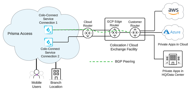
The Colo router advertises its BGP peer IP address to the cloud router, and learns the BGP subnet tunnel from the cloud router. When you first configured the eBGP routing over the VLAN on the customer router, you advertised local reachability for BGP. After the cloud router and the Colo router advertise and learn the routes for the Colo subnet and the local tunnel IP addresses from each other, BGP for the service connection is functional.![]()
![]() To set up routing for the service connections, complete the following steps.
To set up routing for the service connections, complete the following steps.- (Deployments that use GRE tunnels only) Configure GRE on the CPE router. The GRE peer address of the CPE router will correspond to the GRE local address of the service connection, which will be displayed in the Service Endpoint Address column of the service connections page.Make a note of the IP addresses you will use for the Peer Address and Local Address for Connection 1 and, if required, Connection 2 in the service connections.The Local Address will correspond to the eBGP Router column of the service connections page. You use these IP addresses to create a Deny policy that prevents the local BGP IP address to be advertised to the Colo-Connect service connection.Configure Peer groups for the peer and local IP addresses.If you're using a next-generation firewall as the Colo router, go to NetworkVirtual Routers, Add a virtual router, go to BGPPeer Group, and enter the Peer Address as the Peer Address and the Local Address as the Local Address.
![]()
Configure Prisma Access Colo-Connect (Panorama)
Configure a Colo-Connect deployment in Prisma Access.Configure Prisma Access Colo-Connect—Deployments Using Partner Interconnects
To configure Prisma Access Colo-Connect using a partner interconnect, complete these steps.- Create subnets for your Colo-Connect connections.You use the subnets you create here in the connections and service connections that you create in later steps.
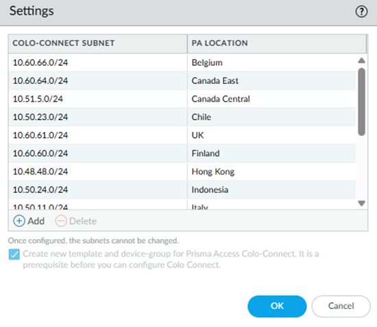
- Go to PanoramaCloud ServicesConfigurationColo-Connect and click the gear icon to edit the settings.Add a Colo-Connect Subnet and select a Prisma Access location (PA Location) for it.Enter a minimum subnet of /28.(Optional) If you plan on creating Colo-Connect instances for more than one location, Add more subnets on a per-location basis.You can configure one subnet per location.Select Create new templates and device-group for Prisma Access Colo-Connect.The first time you configure a Colo-Connect deployment, select this check box so that templates and device groups (Colo_Connect_Template and Colo_Connect_Device_Group, respectively) are created for Colo-Connect. After you create these templates and device groups, this check box is grayed out.
![]() Commit and push your changes.
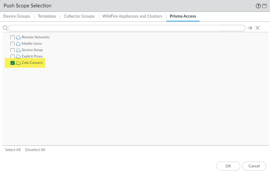
Commit and push your changes.- Go to CommitCommit and Push.Edit Selections and make sure that Colo-Connect is selected in the push scope.
![]() Click OK to save your changes to the Push Scope.Commit and Push your changes.Wait at least three minutes to wait for the subnet configuration changes to populate.Add a new Colo-Connect link (also known as the interconnect).
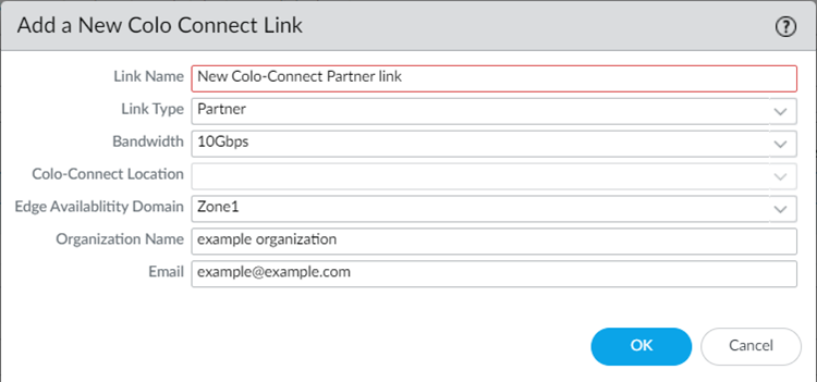
Click OK to save your changes to the Push Scope.Commit and Push your changes.Wait at least three minutes to wait for the subnet configuration changes to populate.Add a new Colo-Connect link (also known as the interconnect).- Go to PanoramaCloud ServicesConfigurationColo-ConnectColo Connect Link and Add a Colo-Connect link.Give the link a unique Link Name.Select a Partner interconnect.You do not need to enter a VLAN ID, your Colo provides one when it uses the pairing key to complete the configuration of your VLAN attachment.Specify the remaining Colo-Connect link parameters.
- Select a Bandwidth for the connection.You can select between 10 Gbps, 20 Gbps, 50 Gbps, or 100 Gbps.If you configure multiple connections for an interconnect, make sure that the total bandwidth of the connections does not exceed the bandwidth of the interconnect. For example, given a partner interconnect of 100 Gbps, you can configure 10 connections of 10 Gbps each, but don't exceed 100 Gbps in total for all connections.If your deployment requires more than 16 Colo-Connect instances, reach out to your Palo Alto Networks account team, who will open an SRE case to accommodate the request.
- Select either Zone1 or Zone2 for the Edge Availability Domain. Take this value from the GCP zone used for your edge availability domain.
- Enter the Organization Name to use for this link.
- Enter the Email to use for this link. Any email address is acceptable.
![]() Add a second link with a different Edge Availability Domain.Create the connections (also known as the VLAN attachments) for Colo-Connect.
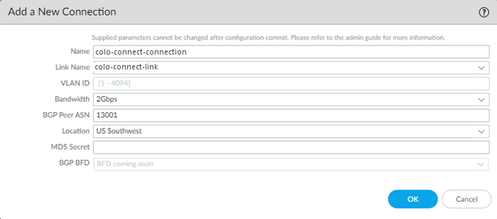
Add a second link with a different Edge Availability Domain.Create the connections (also known as the VLAN attachments) for Colo-Connect.- Go to PanoramaCloud ServicesConfigurationColo-ConnectOnboarding and Add a new connection.Configure the connection settings.
- Enter a unique Name for the connection.
- Select a Link Name from the links you configured in a previous step.
- Select a Bandwidth for the connection.You can select between 1 Gbps, 2 Gbps, 5 Gbps, 10 Gbps, 20 Gbps, 50 Gbps, or 100 Gbps.If you configure multiple connections for an interconnect, make sure that the total bandwidth of the connections does not exceed the bandwidth of the interconnect. For example, given a partner interconnect of 100 Gbps, you can configure 10 connections of 10 Gbps each, but don't exceed 100 Gbps in total for all connections.If your deployment requires more than 16 Colo-Connect instances, reach out to your Palo Alto Networks account team, who will open an SRE case to accommodate the request.
- Enter a BGP Peer ASN. Enter the Autonomous System (AS) number for the customer on-premises router in the Colo. The range is between 1 and 4294967295.
- Select the Location from the
connection names you created in a previous step. You must have already added a subnet for any location you specify.
- (Optional) Enter the BGP MD5
Secret. Disregard the BGP BFD field; it is reserved for a future Colo-Connect release.
![]() Create a second connection.Both connections must be in the same region and one connection each must be in a separate zone. You use these connections in service connections you create in a later step.Commit and push your changes.
Create a second connection.Both connections must be in the same region and one connection each must be in a separate zone. You use these connections in service connections you create in a later step.Commit and push your changes.- Go to CommitCommit and Push.Edit Selections and make sure that Colo-Connect is selected in the push scope.
![]() Click OK to save your changes to the Push Scope.Commit and Push your changes.Retrieve the Pairing Key and complete your partner interconnect configuration in GCP.If you specify 100 Gbps of bandwidth in a connection, you receive four pairing keys, two for each 50 Gbps VLAN attachment.You use this pairing key or keys when you set up the partner interconnect in the Colo.When you first onboard a new connection, the Status in the Colo-Connect Onboarding area shows a Status of PENDING_PARTNER and a BGP Status of DOWN. To bring the connection status to ACTIVE, retrieve the Pairing Key or keys and input in the connection at the Colo.
Click OK to save your changes to the Push Scope.Commit and Push your changes.Retrieve the Pairing Key and complete your partner interconnect configuration in GCP.If you specify 100 Gbps of bandwidth in a connection, you receive four pairing keys, two for each 50 Gbps VLAN attachment.You use this pairing key or keys when you set up the partner interconnect in the Colo.When you first onboard a new connection, the Status in the Colo-Connect Onboarding area shows a Status of PENDING_PARTNER and a BGP Status of DOWN. To bring the connection status to ACTIVE, retrieve the Pairing Key or keys and input in the connection at the Colo.- Go to PanoramaCloud ServicesStatusNetwork DetailsColo Connect and copy the Pairing Key.
![]() Create a new VLAN connection in the Colo (for example, Equinix).
Create a new VLAN connection in the Colo (for example, Equinix).![]() Paste the Pairing Key or keys in the Colo VLAN.GCP detects when the pairing key is consumed, brings the VLAN status to ACTIVE, and generates the BGP IP address for you to configure on your on-premises router in the Colo. These actions initiate eBGP routing over the VLAN between the Colo router and the GCP cloud router.Configure eBGP routing on the Customer (Colo) router for the Colo-Connect connection.You need to set up BGP peering to ensure connectivity between the customer router and the cloud router.Set up the service connections to use with Colo-Connect.Commit and Push your configuration changes, making sure that Colo-Connect is selected in the Push Scope.
Paste the Pairing Key or keys in the Colo VLAN.GCP detects when the pairing key is consumed, brings the VLAN status to ACTIVE, and generates the BGP IP address for you to configure on your on-premises router in the Colo. These actions initiate eBGP routing over the VLAN between the Colo router and the GCP cloud router.Configure eBGP routing on the Customer (Colo) router for the Colo-Connect connection.You need to set up BGP peering to ensure connectivity between the customer router and the cloud router.Set up the service connections to use with Colo-Connect.Commit and Push your configuration changes, making sure that Colo-Connect is selected in the Push Scope.


