Next-Generation Firewall
Configure IPv4 Multicast
Table of Contents
Configure IPv4 Multicast
Configure IPv4 multicast for a logical router (on an Advanced Routing Engine) on a
PAN-OS firewall.
| Where Can I Use This? | What Do I Need? |
|---|---|
|
One of these licenses for Strata Cloud Manager managed NGFWs:
|
The Advanced Routing Engine supports IPv4 multicast for a logical router. Be
familiar with IP Multicast, IGMP, and PIM
concepts.
IPv4 multicast on an Advanced Routing Engine supports features not supported on the
legacy routing engine:
- IGMP static join, which is the ability to specify a static IGMPv3 or IGMPv2 receiver on an interface. The corresponding PIM Join message is sent upstream.
- Protocol Independent Multicast (PIM) supports Reverse-Path Forwarding (RPF) lookup modes: MRIB only, URIB only, and MRIB-then-URIB.
IPv4 multicast does not support IGMPv1.
When you configure IPv4 multicast, you Create Multicast Routing Profiles for PIM interface timers and IGMP interface queries to make your
configuration easier and consistent. You can create multicast route maps to control PIM
group permissions.
You can also Create an IPv4 MRoute if you want unicast traffic to take a different route from
multicast traffic.
PAN-OS
Configure IPv4 multicast for a logical router on a PAN-OS firewall.
Configure IPv4 multicast for a logical router on a PAN-OS firewall.
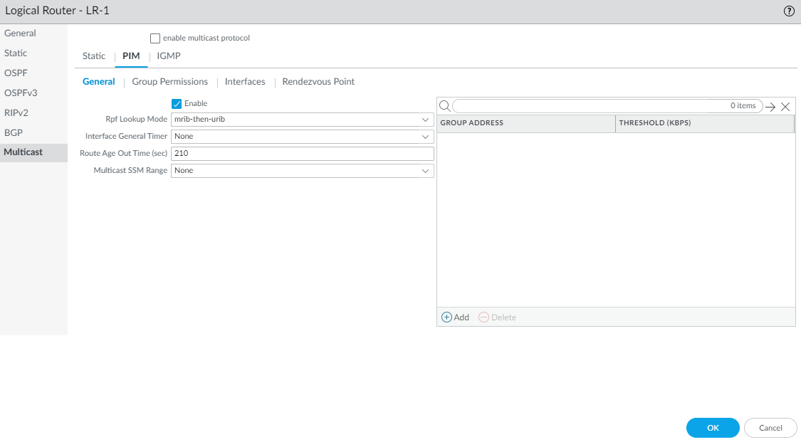
- Configure a Logical Router.Select and select a logical router.Select Multicast and enable multicast protocol.Configure general PIM parameters for the logical router.
- Select and Enable PIM.
![]() Select the RPF lookup mode, which determines where the logical router looks to find the outgoing interface to reach the source address contained in the multicast packet. If the outgoing interface stored in the RIB matches the interface on which the multicast packet arrived, the logical router accepts and forwards the packet; otherwise, it drops the packet.
Select the RPF lookup mode, which determines where the logical router looks to find the outgoing interface to reach the source address contained in the multicast packet. If the outgoing interface stored in the RIB matches the interface on which the multicast packet arrived, the logical router accepts and forwards the packet; otherwise, it drops the packet.- mrib-only—Look in multicast RIB only.
- mrib-then-urib—Look in multicast RIB first; if route is not present in multicast RIB, then look in unicast RIB.
- urib-only—Look in unicast RIB only.
The RPF lookup mode also controls where to do route lookup to select the route to use for the PIM Join.For the Interface General Timer, select a PIM Interface Timer Profile or create a new IPv4 PIM Interface Timer profile; default is None.Specify the Route Age Out Time (sec)—the number of seconds that a multicast route remains in the mRIB after the session ends between a multicast group and a source; range is 210 to 7,200; default is 210.To configure Source-Specific Multicast (SSM), in Multicast SSM Range select a prefix list (or create a new one) that specifies the source addresses allowed to deliver multicast traffic to the receiver; default is None (no prefix list).To configure the Shortest-Path Tree (SPT) threshold for a multicast group or prefix, Add a Group Address (multicast group or prefix for which you are specifying the distribution tree) by selecting a Prefix List or creating a new one.Specify the Threshold rate in kilobits per second (kbps); if multicast traffic for the multicast group/prefix arrives at the logical router faster than this threshold rate, routing to the specified group/prefix switches from shared tree (sourced from the Rendezvous Point [RP]) to SPT distribution:- 0 (switch on first data packet) (default)—The logical router switches from shared tree to SPT for the group/prefix when the logical router receives the first data packet for the group/prefix.
- Enter the total number of kilobits per second that can arrive for the multicast group/prefix at any interface and over any time period, upon which the logical router switches to SPT distribution for that multicast group or prefix; range is 0 to 4,294,967,295.
- never (do not switch to spt)—The PIM router continues to use the shared tree to forward packets to the multicast group/prefix.
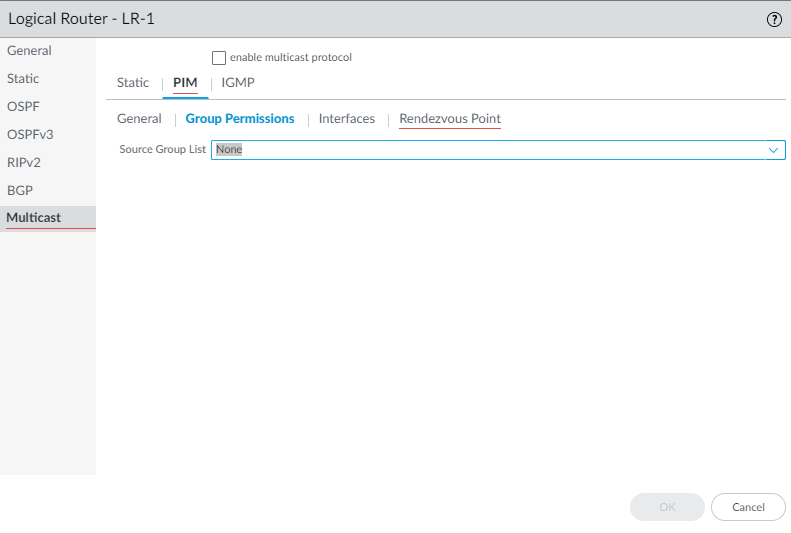
Specify PIM group permissions to control which PIM Join messages and Register messages the logical router accepts, and which multicast traffic the logical router forwards.- Select .To control packets to certain destination multicast groups from certain sources (S,G) to transit the logical router, for Source Group List, select an Access List that you created or create a new one. The access list can be an extended access list where the source specifies the multicast source and the destination specifies the multicast group. Default is None (no access list).
![]() When you modify PIM Group Permissions by removing or changing the Source Group access list, the new permission does not retroactively clear multicast routes form the multicast RIB table (mRIB) or multicast FIB table (mFIB) for existing flows. To change entries for existing flows in the mRIB or mFIB, you would need to force a Leave or clear mroute entry.Configure PIM characteristics for an interface.
When you modify PIM Group Permissions by removing or changing the Source Group access list, the new permission does not retroactively clear multicast routes form the multicast RIB table (mRIB) or multicast FIB table (mFIB) for existing flows. To change entries for existing flows in the mRIB or mFIB, you would need to force a Leave or clear mroute entry.Configure PIM characteristics for an interface.- Select and Add an interface by Name.
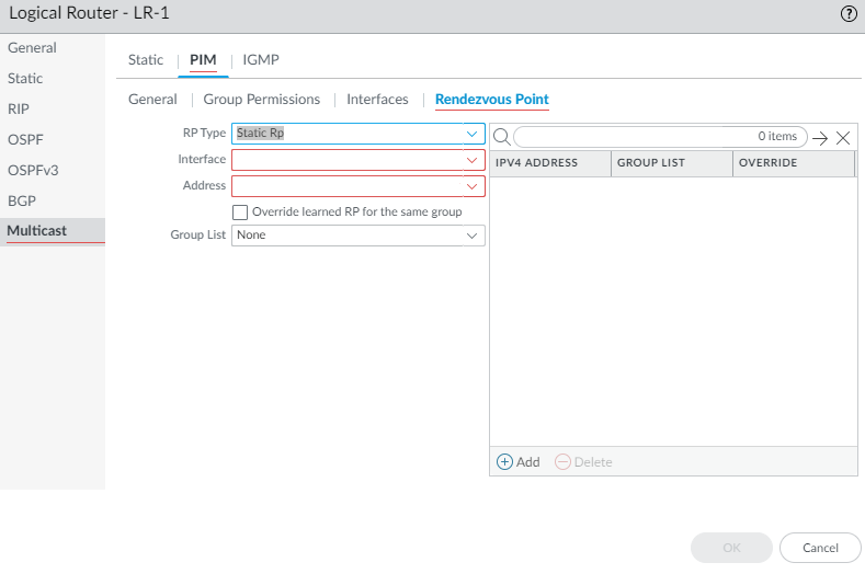
![]() Enter a helpful Description of the interface.Specify the DR Priority (Designated Router priority) of the interface to control which router forwards PIM Join messages, PIM Register messages, and Prune messages to the Rendezvous Point (RP); range is 1 to 4,294,967,295; default is 1. Of the PIM devices on a LAN, if DR Priority is configured, the device with the highest priority value is elected the DR.Send BSM to allow propagation of Bootstrap Messages (enabled by default).The Advanced Routing Engine cannot act as a BSR, but can send and relay BSM messages.The Timer Profile for the interface is inherited from the General PIM section unless you override that by selecting an IPv4 PIM Interface Timer profile; default is None.Specify a Neighbor Filter using an access list you created or create a new access list to specify the prefixes of devices that are allowed to become or denied from becoming PIM neighbors of the logical router.Click OK.(ASM only) Configure a PIM Rendezvous Point (RP) for an Any-Source Multicast (ASM) environment.You can configure a Candidate RP and a Static RP; they are not mutually exclusive.
Enter a helpful Description of the interface.Specify the DR Priority (Designated Router priority) of the interface to control which router forwards PIM Join messages, PIM Register messages, and Prune messages to the Rendezvous Point (RP); range is 1 to 4,294,967,295; default is 1. Of the PIM devices on a LAN, if DR Priority is configured, the device with the highest priority value is elected the DR.Send BSM to allow propagation of Bootstrap Messages (enabled by default).The Advanced Routing Engine cannot act as a BSR, but can send and relay BSM messages.The Timer Profile for the interface is inherited from the General PIM section unless you override that by selecting an IPv4 PIM Interface Timer profile; default is None.Specify a Neighbor Filter using an access list you created or create a new access list to specify the prefixes of devices that are allowed to become or denied from becoming PIM neighbors of the logical router.Click OK.(ASM only) Configure a PIM Rendezvous Point (RP) for an Any-Source Multicast (ASM) environment.You can configure a Candidate RP and a Static RP; they are not mutually exclusive.- Select .Select the local RP Type: Static RP or Candidate RP; default is None.If you choose Static RP, this establishes a static mapping of an RP to multicast groups. You must explicitly configure the same RP on other PIM routers in the PIM domain. Configure the following:
- Select the RP Interface where the RP receives and sends multicast packets. Valid interface types are Layer3 interfaces (which include Ethernet, VLAN, loopback, Aggregate Ethernet (AE), tunnel, and subinterfaces).
- Select the Address of the interface; the IP addresses of the interface you selected populate the list.
- Select Override learned RP for the same group so that this static RP serves as RP instead of the RP elected for the groups in the Group List.
- Specify the Group List of multicast groups for which the static RP acts as the RP by selecting an Access List or creating a new access list. Default is None (no access list).
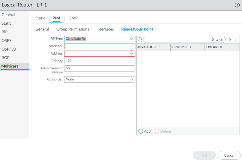
![]() If you choose Candidate RP:
If you choose Candidate RP:- Select the Interface where the candidate RP receives and sends multicast packets. Valid interface types are Layer3 interfaces (which include Ethernet, VLAN, loopback, Aggregate Ethernet (AE), tunnel, and subinterfaces).
- Select the Address of the interface.
- Specify the Priority of the candidate RP; range is 0 to 255; default is 192. A lower priority value indicates a higher priority.
- Specify the Advertisement Interval, the frequency (in seconds) at which the candidate RP sends advertisements to other routers; range is 1 to 26,214; default is 60.
- To control the groups that the candidate RP accepts, select a Group List, which is an IPv4 access list you created, or create a new access list. Default is None (no access list). If no access list is applied, the logical router starts advertising itself as the RP for all groups.
![]() Add an IPv4 Address of the remote (external) RP.Select a Group List to specify the multicast groups for which the remote RP acts as the RP or create a new access list. Default is None (no access list).Select Override if you want the remote RP you statically configured to serve as RP instead of an RP that is dynamically learned (elected) for the groups in the Group List.Click OK.Click OK to save PIM settings.Configure IGMP on interfaces that face a multicast receiver.
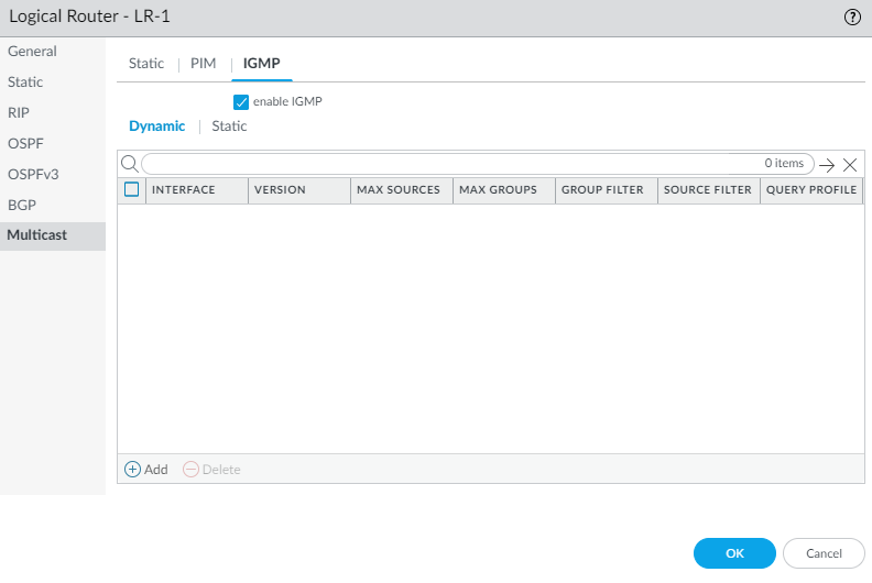
Add an IPv4 Address of the remote (external) RP.Select a Group List to specify the multicast groups for which the remote RP acts as the RP or create a new access list. Default is None (no access list).Select Override if you want the remote RP you statically configured to serve as RP instead of an RP that is dynamically learned (elected) for the groups in the Group List.Click OK.Click OK to save PIM settings.Configure IGMP on interfaces that face a multicast receiver.- Select IGMP and enable IGMP.
![]() To configure a dynamic IGMP interface, select Dynamic.
To configure a dynamic IGMP interface, select Dynamic.- Add an Interface
by selecting one from the list.
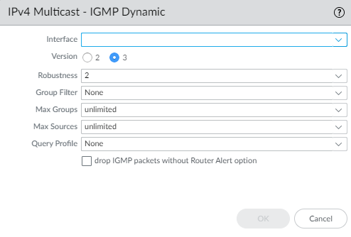
![]()
- Select the IGMP Version: 2 or 3.
- Select the Robustness value in the range
1 to 7; default is 2. The (Robustness * QueryInterval) + MaxQueryResponseTime determines how long a Join message is valid on the logical router. If the logical router receives a Leave Group message, Robustness * LastMemberQueryInterval is the length of time that the logical router waits before deleting the Leave Group entry. Increase the Robustness value if the subnet on which this logical router is located is prone to losing packets. For Join messages, a Robustness value of 1 is ignored. For Leave Group messages, the logical router uses the Robustness value as the Last Member Query Count also.
- For Group Filter, select an access list or create a new access list to control the sources and groups for which the interface will accept IGMP Joins; default is None (no access list).
- For Max Groups, enter the maximum number of groups that IGMP can process simultaneously for the interface. Range is 1 to 65,535; default is unlimited, which means the highest value in the range.
- For Max Sources, enter the maximum number of sources that IGMP can process simultaneously for the interface. Range is 1 to 65,535; default is unlimited, which means the highest value in the range.
- For Query Profile, select an IGMP Interface Query profile you created or create a new one to apply to the interface; default is None.
- Select drop IGMP packets without Router Alert option to require that incoming IGMPv2 or IGMPv3 packets have the IP Router Alert Option, RFC 2113, or they will be dropped. (Default is disabled.)
- Click OK to save the dynamic IGMP interface.
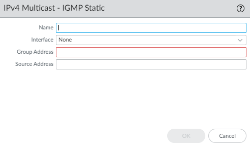
To configure a static IGMP interface, select Static.- Add a static interface by
Name.
![]()
- Select the Interface to be the static IGMP interface.
- Enter the multicast Group Address of the static IGMP members.
- Enter the Source Address of the sender transmitting multicast traffic to the multicast group (S,G). Traffic for this (S,G) combination is allowed on the static IGMP interface.
- Click OK to save the static IGMP interface.
Click OK to save the multicast configuration.Commit.Strata Cloud Manager
Configure a logical router on Strata Cloud Manager with IPv4 multicast routing.Use this procedure to configure a logical router on Strata Cloud Manager with IPv4 multicast routing. This procedure assumes you have already configured a logical router.- Select .For Configuration Scope, select Folders and then select All Firewalls, a specific folder, or the specific firewalls you want to configure. (Don’t choose Global.)Select and select the logical router you're configuring.Edit the Multicast card and Enable multicast.Configure general PIM parameters for the logical router.
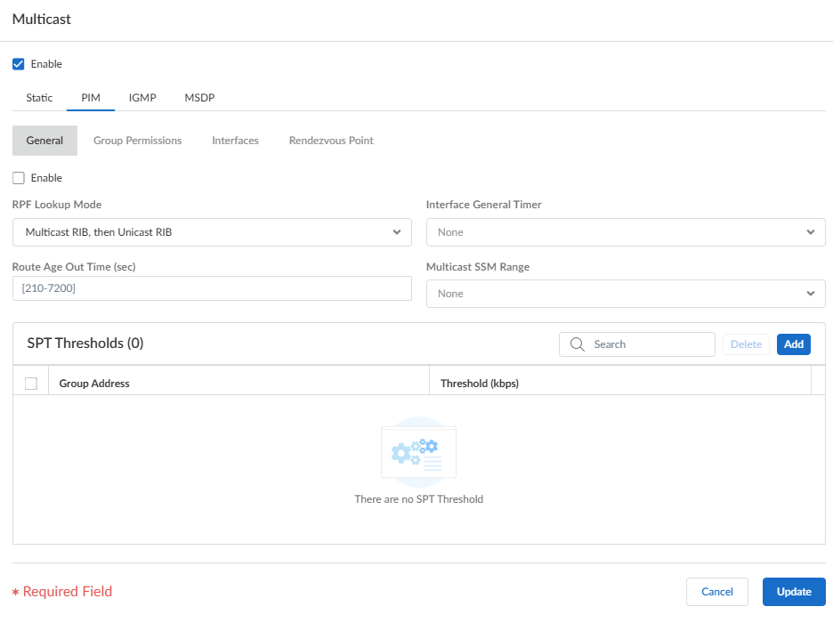
- Select and Enable PIM.
![]() Select the RPF lookup mode, which determines where the logical router looks to find the outgoing interface to reach the source address contained in the multicast packet. If the outgoing interface stored in the RIB matches the interface on which the multicast packet arrived, the logical router accepts and forwards the packet; otherwise, it drops the packet.
Select the RPF lookup mode, which determines where the logical router looks to find the outgoing interface to reach the source address contained in the multicast packet. If the outgoing interface stored in the RIB matches the interface on which the multicast packet arrived, the logical router accepts and forwards the packet; otherwise, it drops the packet.- Multicast RIB, then Unicast RIB—Look in multicast RIB first; if the route isn’t present in multicast RIB, then look in unicast RIB.
- Multicast RIB only—Look in multicast RIB only.
- Unicast RIB only—Look in unicast RIB only.
The RPF lookup mode also controls where to do route lookup to select the route to use for the PIM Join.For the Interface General Timer, select a PIM Interface Timer Profile or create a new IPv4 PIM Interface Timer profile; default is None.Specify the Route Age Out Time (sec)—the number of seconds that a multicast route remains in the mRIB after the session ends between a multicast group and a source; range is 210 to 7,200; the default is 210.To configure source-specific multicast (SSM), in Multicast SSM Range select a prefix list (or create a new one) that specifies the source addresses allowed to deliver multicast traffic to the receiver. The default is None (no prefix list).To configure the Shortest-Path Tree (SPT) threshold for a multicast group or prefix, Add a Group Address (multicast group or prefix for which you're specifying the distribution tree) by selecting a prefix list or creating a new prefix list.![]() Specify the Threshold rate in kilobits per second (kbps) by selecting one of the following choices. If multicast traffic for the multicast group/prefix arrives at the logical router faster than this threshold rate, routing to the specified group/prefix switches from shared tree (sourced from the Rendezvous Point [RP]) to SPT distribution.
Specify the Threshold rate in kilobits per second (kbps) by selecting one of the following choices. If multicast traffic for the multicast group/prefix arrives at the logical router faster than this threshold rate, routing to the specified group/prefix switches from shared tree (sourced from the Rendezvous Point [RP]) to SPT distribution.- 0 (switch on first data packet) (default)—The logical router switches from shared tree to SPT for the group/prefix when the logical router receives the first data packet for the group/prefix.
- Enter the total number of kilobits per second that can arrive for the multicast group/prefix at any interface and over any time period, upon which the logical router switches to SPT distribution for that multicast group or prefix. The range is 0 to 4,294,967,295.
- never (do not switch to spt)—The PIM router continues to use the shared tree to forward packets to the multicast group/prefix.
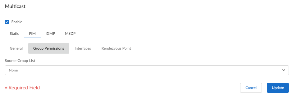
Specify PIM group permissions to control which PIM Join messages and Register messages the logical router accepts, and which multicast traffic the logical router forwards.- Select .To control packets to certain destination multicast groups from certain sources (S,G) to transit the logical router, for Source Group List, select an access list that you created or create a new access list. The access list can be an extended access list where the source specifies the multicast source and the destination specifies the multicast group. The default is None (no access list).
![]() When you modify PIM group permissions by removing or changing the Source Group access list, the new permission does not retroactively clear multicast routes form the multicast RIB table (mRIB) or multicast FIB table (mFIB) for existing flows. To change entries for existing flows in the mRIB or mFIB, you would need to force a Leave or clear mroute entry.Configure PIM characteristics for an interface.
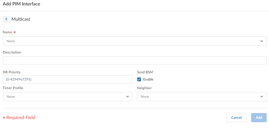
When you modify PIM group permissions by removing or changing the Source Group access list, the new permission does not retroactively clear multicast routes form the multicast RIB table (mRIB) or multicast FIB table (mFIB) for existing flows. To change entries for existing flows in the mRIB or mFIB, you would need to force a Leave or clear mroute entry.Configure PIM characteristics for an interface.- Select and Add an interface by Name.
![]() Enter a helpful Description of the interface.Specify the DR Priority (designated router priority) of the interface to control which router forwards PIM Join messages, PIM Register messages, and Prune messages to the Rendezvous Point (RP); the range is 1 to 4,294,967,295; the default is 1. Of the PIM devices on a LAN, if DR Priority is configured, the device with the highest priority value is elected as the DR.Send BSM to allow propagation of Bootstrap Messages (enabled by default).The Advanced Routing Engine can’t act as a BSR, but can send and relay BSM messages.The Timer Profile for the interface is inherited from the General PIM section unless you override that by selecting an IPv4 PIM Interface Timer profile; the default is None.Specify a Neighbor filter using a prefix list you created or create a new access list to specify the prefixes of devices that are allowed to become or denied from becoming PIM neighbors of the logical router. The default is None (no prefix list).Click Update.(ASM only) Configure a PIM Rendezvous Point (RP) for an Any-Source Multicast (ASM) environment.You can configure a candidate RP and a static RP; they aren't mutually exclusive.
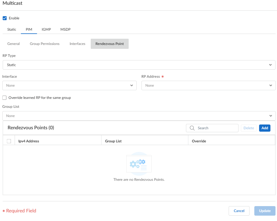
Enter a helpful Description of the interface.Specify the DR Priority (designated router priority) of the interface to control which router forwards PIM Join messages, PIM Register messages, and Prune messages to the Rendezvous Point (RP); the range is 1 to 4,294,967,295; the default is 1. Of the PIM devices on a LAN, if DR Priority is configured, the device with the highest priority value is elected as the DR.Send BSM to allow propagation of Bootstrap Messages (enabled by default).The Advanced Routing Engine can’t act as a BSR, but can send and relay BSM messages.The Timer Profile for the interface is inherited from the General PIM section unless you override that by selecting an IPv4 PIM Interface Timer profile; the default is None.Specify a Neighbor filter using a prefix list you created or create a new access list to specify the prefixes of devices that are allowed to become or denied from becoming PIM neighbors of the logical router. The default is None (no prefix list).Click Update.(ASM only) Configure a PIM Rendezvous Point (RP) for an Any-Source Multicast (ASM) environment.You can configure a candidate RP and a static RP; they aren't mutually exclusive.- Select .Select the local RP Type: Static RP or Candidate RP; default is None.If you choose Static RP, this establishes a static mapping of an RP to multicast groups. Explicitly configure the same RP on other PIM routers in the PIM domain. Configure the following:
- Select the RP Interface where the RP receives and sends multicast packets. Valid interface types are Layer 3 interfaces (which include Ethernet, VLAN, loopback, Aggregate Ethernet (AE), tunnel, and subinterfaces).
- Select the RP Address of the interface; the IP addresses of the interface you selected populate the list.
- Select Override learned RP for the same group so that this static RP serves as RP instead of the RP elected for the groups in the Group List.
- Specify the Group List of multicast groups for which the static RP acts as the RP by selecting an access list or creating a new access list. The default is None (no access list).
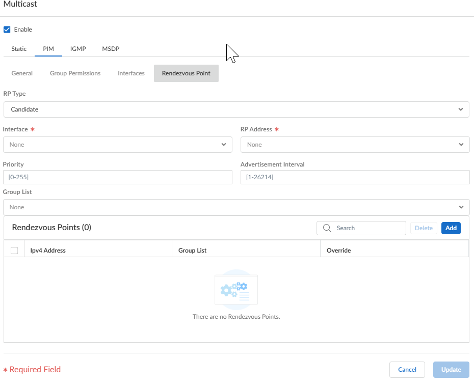
![]() If you choose Candidate RP:
If you choose Candidate RP:- Select the Interface where the candidate RP receives and sends multicast packets. Valid interface types are Layer 3 interfaces (which include Ethernet, VLAN, loopback, Aggregate Ethernet (AE), tunnel, and subinterfaces).
- Select the RP Address of the interface.
- Specify the Priority of the candidate RP; the range is 0 to 255; the default is 192. A lower priority value indicates a higher priority.
- Specify the Advertisement Interval, the frequency (in seconds) at which the candidate RP sends advertisements to other routers; range is 1 to 26,214; the default is 60.
- To control the groups that the candidate RP accepts, select a Group List, which is an IPv4 access list you created, or create a new access list. The default is None (no access list). If you don't apply an access list, the logical router starts advertising itself as the RP for all groups.
![]() Add an IP Address of the remote (external) RP or use a variable.Specify a Group List by selecting an access list to specify the multicast groups for which the remote RP acts as the RP or create a new access list. The default is None (no access list).Select Override learned RP for the same group if you want the remote RP you statically configured to serve as RP instead of an RP that is dynamically learned (elected) for the groups in the Group List.Click Add.Click Update to save the PIM settings.Configure IGMP on interfaces that face a multicast receiver.
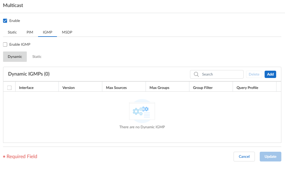
Add an IP Address of the remote (external) RP or use a variable.Specify a Group List by selecting an access list to specify the multicast groups for which the remote RP acts as the RP or create a new access list. The default is None (no access list).Select Override learned RP for the same group if you want the remote RP you statically configured to serve as RP instead of an RP that is dynamically learned (elected) for the groups in the Group List.Click Add.Click Update to save the PIM settings.Configure IGMP on interfaces that face a multicast receiver.- Select IGMP and Enable IGMP.To configure a dynamic IGMP interface, select Dynamic.
![]()
- Add an Interface
by selecting one from the list.
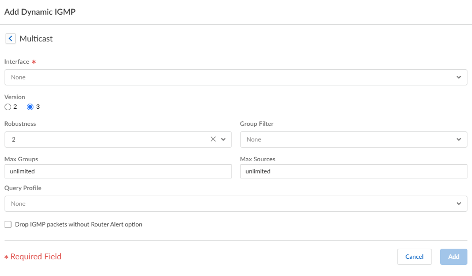
![]()
- Select the IGMP Version: 2 or 3.
- Select the Robustness value in the range
1 to 7; the default is 2. The (Robustness * QueryInterval) + MaxQueryResponseTime determines how long a Join message is valid on the logical router. If the logical router receives a Leave Group message, Robustness * LastMemberQueryInterval is the length of time that the logical router waits before deleting the Leave Group entry. Increase the Robustness value if the subnet on which this logical router is located is prone to losing packets. For Join messages, a Robustness value of 1 is ignored. For Leave Group messages, the logical router uses the Robustness value as the Last Member Query Count also.
- For Group Filter, select an access list or create a new access list to control the sources and groups for which the interface will accept IGMP Joins; the default is None (no access list).
- For Max Groups, enter the maximum number of groups that IGMP can process simultaneously for the interface. The range is 1 to 65,535; the default is unlimited, which means the highest value in the range.
- For Max Sources, enter the maximum number of sources that IGMP can process simultaneously for the interface. The range is 1 to 65,535; the default is unlimited, which means the highest value in the range.
- For Query Profile, select an IGMP Interface Query profile that you created or create another IGMP Interface Query profile to apply to the interface; the default is None.
- Select Drop IGMP packets without Router Alert option to require that incoming IGMPv2 or IGMPv3 packets have the IP Router Alert Option, RFC 2113, or they will be dropped. (The default is disabled.)
- Click Add to save the dynamic IGMP interface.
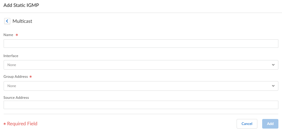
To configure a static IGMP interface, select Static.- Add a static interface by
Name.
![]()
- Select the Interface to be the static IGMP interface.
- Enter the multicast Group Address of the static IGMP members.
- Enter the Source Address of the sender transmitting multicast traffic to the multicast group (S,G). Traffic for this (S,G) combination is allowed on the static IGMP interface.
- Click Add to save the static IGMP interface.
Click Update to save the IGMP configuration.Click Save.Push Config and Push the configuration. Select the Admin Scope and enter a Description for the configuration. Select Push again.