Configure a Virtual SD-WAN Interface
Table of Contents
Configure a Virtual SD-WAN Interface
If you aren’t using Auto VPN configuration with Panorama,
configure a virtual SD-WAN interface to group multiple SD-WAN-capable
Ethernet interfaces.
If you use Auto VPN configuration through
Panorama, it creates the SD-WAN interfaces for you, in which case
you don’t create and configure a virtual SD-WAN interface.
If
you aren’t using Auto VPN configuration with Panorama, create and
configure a virtual SD-WAN interface to specify one or more physical, SD-WAN-capable ethernet interfaces that
go to the same destination, such as to a specific hub or to the
internet. In fact, all links in a virtual SD-WAN interface must
be the same type: all VPN tunnel links or all direct internet access
(DIA) links.
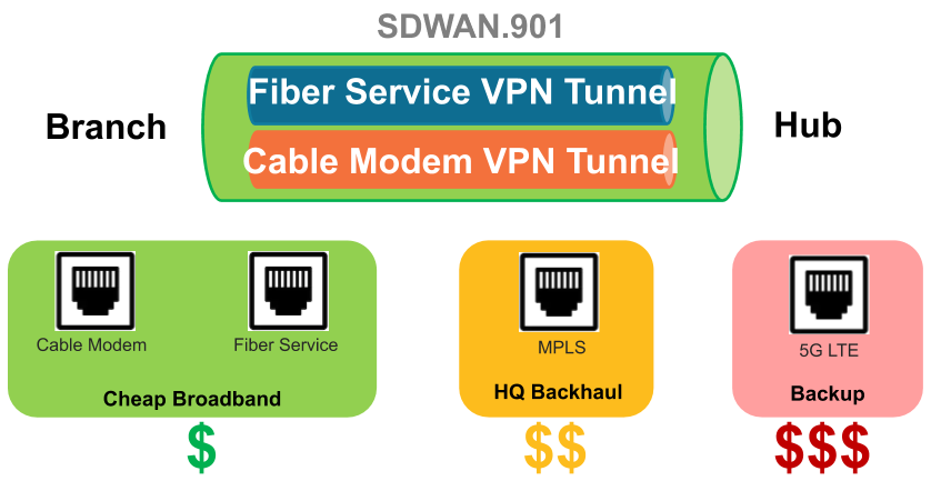
The first figure illustrates an example of an SD-WAN interface named SDWAN.901 that bundles two
physical interfaces, which use different carriers: Ethernet1/1 (the cable modem
link) and Ethernet1/2 (the fiber service link). Both links are a VPN tunnel from the
branch to the hub.
In this figure, both links
in the SD-WAN interface happen to use the same link tag (Cheap Broadband),
but links in an SD-WAN interface can have different link tags.
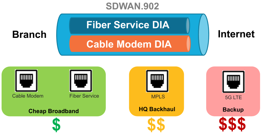
In the following figure, SDWAN.902 bundles Ethernet1/1 and Ethernet1/2 links, which are both DIA
links from the branch to the internet:
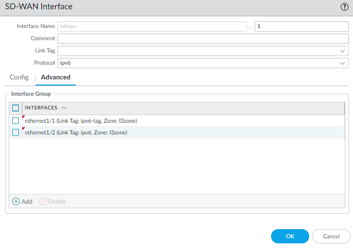
- Log in to the Panorama Web Interface.Select and select the appropriate template from the Template context drop-down.Add a logical SD-WAN interface by entering a number (in the range 1 to 9,999) after the sdwan. prefix.Auto VPN configuration creates SD-WAN interfaces numbered .901, .902, and so on. Hence, if you want to create the SD-WAN interfaces manually, don't use the sdwan.90x format for an SD-WAN interface name. Similarly, Auto VPN configuration creates an SD-WAN interface numbered .9016 for an IPv6 interface, so don't use sdwan.9016 for an SD-WAN interface name.Enter a descriptive Comment.Add a helpful comment, such as Branch to internet or Branch to western USA hub if you are on the Branch template. Your comment makes troubleshooting easier rather than trying to decipher auto-generated names in logs and reports.Select the Protocol to indicate the type of virtual SD-WAN interface:
- ipv4 indicates an IPv4 DIA virtual interface.
- ipv6 indicates an IPv6 DIA virtual interface.
- none indicates a VPN tunnel virtual interface.
On the Config tab, assign the SD-WAN interface to a Virtual Router.Assign the SD-WAN interface to a Security Zone.The virtual SD-WAN interface and all of its interface members must be in the same Security zone, thus ensuring the same Security policy rules apply to all paths from the branch to the same destination.On the Advanced tab, Add Interfaces, which are members that go to the same destination, by selecting one or more Layer 3 Ethernet interfaces (for DIA) or one more virtual VPN tunnel interfaces (for hub). If you enter more than one interface, they must all be the same type (either VPN tunnel or DIA).The firewall virtual router uses this virtual SD-WAN interface to route SD-WAN traffic to a DIA or a hub location. During routing, the route table determines which virtual SD-WAN interface (egress interface) the packet will exit based on the destination IP address in the packet. Then the SD-WAN path health and Traffic Distribution profiles in the SD-WAN policy rule that the packet matches determine which path to use (and the order in which to consider new paths if a path deteriorates.)Click OK to save your configuration change.![]() Commit and Commit and Push your configuration changes.
Commit and Commit and Push your configuration changes.