Configure an Aggregate Ethernet Interface and Subinterfaces for SD-WAN
Table of Contents
Configure an Aggregate Ethernet Interface and Subinterfaces for SD-WAN
SD-WAN supports AE interfaces for link redundancy and
tagged Layer 3 subinterfaces for traffic segmentation.
Physical firewalls running PAN-OS 11.0 and
SD-WAN Plugin 2.1.0 support SD-WAN on aggregated Ethernet (AE) interfaces
so that an SD-WAN firewall in a data center, for example, can have
an aggregate interface group (bundle) of physical Ethernet interfaces
that provide link redundancy. SD-WAN supports AE interfaces with
or without subinterfaces. You can create an AE interface with subinterfaces
that you can tag for different ISP services in order to provide
end-to-end traffic segmentation. Thus, your ISP services can reach
multiple labs or buildings without needing a dedicated pair of fibers
for each connection. A Layer 3 AE interface group connects to a
router, as shown in the following figure:

VM-Series
firewalls do not support AE interfaces. An SD-WAN hub or branch
firewall that has an AE interface should not belong to the same
VPN cluster as a VM-Series SD-WAN hub or branch firewall because
AE interfaces are not supported on VM-Series firewalls.
PPPoE
is not supported on subinterfaces.
- Log in to the Panorama Web Interface.Configure an SD-WAN Interface Profile for each ISP connection (subinterface) in the AE interface group to define its link attributes.Create an AE interface group.
- Select , select a Panorama Template, and Add Aggregate Group.For Interface Name, enter the number to identify the aggregate group; range is 1 to 16.For Interface Type, select Layer3.Click OK.Assign physical interfaces to the aggregate group.
- Select and select the interface you want to assign to the aggregate group.Select the Interface Type as Aggregate Ethernet.Select the Aggregate Group you created; for example, ae1.On the Advanced tab, select the Link Speed, Link Duplex, and Link State.Click OK.Repeat this step for each interface you want to assign to the aggregate group.For the aggregate group, create a subinterface that uses a static IP address.
- Select , highlight the aggregate interface, such as ae1, and click Add Subinterface at the bottom of the screen.For Interface Name, enter a number after the period, such as 107.Enter the VLAN Tag to differentiate between the subinterfaces. For ease of use, make the tag the same number as the subinterface ID.To configure a static IPv4 address for the subinterface, select the IPv4 tab and Enable SD-WAN.
![]() Select the Type of address: Static.Add the IP address (and subnet mask) of the subinterface.Enter the IP address of the Next Hop Gateway.To configure a static IPv6 address for the subinterface, select the IPv6 tab, Enable IPv6 on the interface, and Enable SD-WAN.
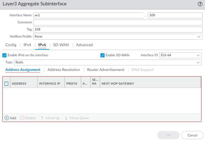
Select the Type of address: Static.Add the IP address (and subnet mask) of the subinterface.Enter the IP address of the Next Hop Gateway.To configure a static IPv6 address for the subinterface, select the IPv6 tab, Enable IPv6 on the interface, and Enable SD-WAN.![]() In the EUI-64 (default 64-bit Extended Unique Identifier) field, enter the 64-bit EUI in hexadecimal format. If you leave this field blank, the firewall uses the EUI-64 generated from the MAC address of the physical interface. If you enable the Use interface ID as host portion option when added an address, the firewall uses the Interface ID as the host portion of that address.SelectAddress Assignment and Add an IPv6 Address for the interface or select New Variable to create the variable.
In the EUI-64 (default 64-bit Extended Unique Identifier) field, enter the 64-bit EUI in hexadecimal format. If you leave this field blank, the firewall uses the EUI-64 generated from the MAC address of the physical interface. If you enable the Use interface ID as host portion option when added an address, the firewall uses the Interface ID as the host portion of that address.SelectAddress Assignment and Add an IPv6 Address for the interface or select New Variable to create the variable.![]() Use interface ID as host portion; see prior substep for EUI-64.Select Anycast to make the IPv6 address (route) an Anycast address (route), which means multiple locations can advertise the same prefix, and IPv6 sends the anycast traffic to the node it considers the nearest, based on routing protocol costs and other factors.Enter the IPv6 address of the Next Hop Gateway (the next hop from the IPv6 address you entered). The Next Hop Gateway must be on the same subnet as the IPv6 address. The Next Hop Gateway is the IP address of the ISP's default router that the ISP gave you when you bought the service. It is the next hop IP address to which the firewall sends traffic to reach the ISP's network, and ultimately, the internet and the hub.Select Send Router Advertisement to enable the firewall to send this address in Router Advertisements (RAs), in which case you must also enable the global Enable Router Advertisement option for the interface (on the Router Advertisement tab).Enter the Valid Lifetime (sec) in seconds that the firewall considers the address valid. The valid lifetime must equal or exceed the Preferred Lifetime (sec) (default is 2,592,000).Enter the Preferred Lifetime (sec) (in seconds) that the valid address is preferred, which means the firewall can use it to send and receive traffic. After the preferred lifetime expires, the firewall can't use the address to establish new connections, but any existing connections are valid until the valid lifetime expires (default is 604,800).Select On-link if systems that have addresses within the prefix are reachable without a router.Select Autonomous if systems can independently create an IP address by combining the advertised prefix with the Interface ID.Click OK.As an alternative to a static address, for the aggregate group, create a subinterface that uses DHCP to get its address.
Use interface ID as host portion; see prior substep for EUI-64.Select Anycast to make the IPv6 address (route) an Anycast address (route), which means multiple locations can advertise the same prefix, and IPv6 sends the anycast traffic to the node it considers the nearest, based on routing protocol costs and other factors.Enter the IPv6 address of the Next Hop Gateway (the next hop from the IPv6 address you entered). The Next Hop Gateway must be on the same subnet as the IPv6 address. The Next Hop Gateway is the IP address of the ISP's default router that the ISP gave you when you bought the service. It is the next hop IP address to which the firewall sends traffic to reach the ISP's network, and ultimately, the internet and the hub.Select Send Router Advertisement to enable the firewall to send this address in Router Advertisements (RAs), in which case you must also enable the global Enable Router Advertisement option for the interface (on the Router Advertisement tab).Enter the Valid Lifetime (sec) in seconds that the firewall considers the address valid. The valid lifetime must equal or exceed the Preferred Lifetime (sec) (default is 2,592,000).Enter the Preferred Lifetime (sec) (in seconds) that the valid address is preferred, which means the firewall can use it to send and receive traffic. After the preferred lifetime expires, the firewall can't use the address to establish new connections, but any existing connections are valid until the valid lifetime expires (default is 604,800).Select On-link if systems that have addresses within the prefix are reachable without a router.Select Autonomous if systems can independently create an IP address by combining the advertised prefix with the Interface ID.Click OK.As an alternative to a static address, for the aggregate group, create a subinterface that uses DHCP to get its address.- Select and in the Template field, select a Template Stack.Highlight the aggregate interface, such as ae1, and click Add Subinterface at the bottom of the screen.Highlight the subinterface and click Override at the bottom of the screen.Highlight the subinterface and for Interface Name, enter a number after the period, such as 1.Enter the VLAN Tag to differentiate between the subinterfaces. For ease of use, make the tag the same number as the subinterface ID.Select the IPv4 tab and Enable SD-WAN.A subinterface in an aggregated interface group supports only an IPv4 address as a DHCP client, not an IPv6 address.Select the Type of address: DHCP Client.Select Enable.Uncheck (do not select) Automatically create default route pointing to default gateway provided by server.Select the Advanced tab and DDNS tab.Select Settings and Enable. The Hostname is automatically generated by the Panorama SD-WAN plugin.Select the Vendor as Palo Alto Networks DDNS.Click OK.
![]() Apply an SD-WAN Interface Profile to the subinterface.
Apply an SD-WAN Interface Profile to the subinterface.- Highlight the subinterface you created and select the SD-WAN tab.Select the SD-WAN Interface Profile you created for this link or create a new profile.
![]() Click OK.Repeat the prior steps to create additional Layer3 subinterfaces for the aggregate interface group and apply an SD-WAN Interface Profile to each subinterface.Commit.
Click OK.Repeat the prior steps to create additional Layer3 subinterfaces for the aggregate interface group and apply an SD-WAN Interface Profile to each subinterface.Commit.