Network Security
Site-to-Site VPN with Static and Dynamic Routing
Table of Contents
Site-to-Site VPN with Static and Dynamic Routing
| Where Can I Use This? | What Do I Need? |
|---|---|
| No license required |
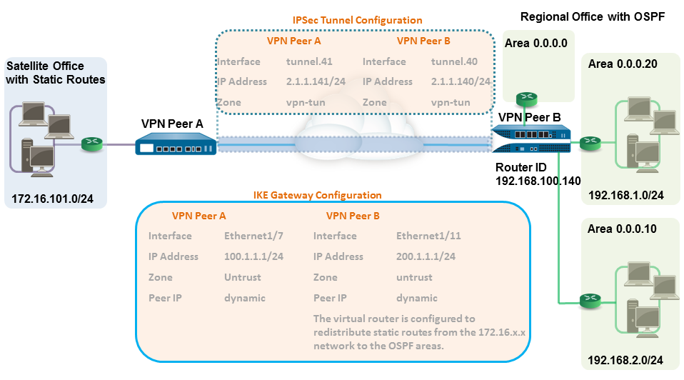
In this example, one site uses static routes and the other site uses OSPF. When the routing
protocol isn’t the same between the locations, the tunnel interface on each firewall
must be configured with a static IP address. Then, to allow the exchange of routing
information, the firewall that participates in both the static and dynamic routing
process must be configured with a Redistribution profile. Configuring the
redistribution profile enables the virtual router to redistribute and filter routes
between protocols—static routes, connected routes, and hosts— from the static
autonomous system to the OSPF autonomous system. Without this redistribution
profile, each protocol functions on its own and doesn’t exchange any route
information with other protocols running on the same virtual router.
In
this example, the satellite office has static routes and all traffic
destined to the 192.168.x.x network is routed to tunnel.41. The
virtual router on VPN Peer B participates in both the static and
the dynamic routing process and is configured with a redistribution
profile in order to propagate (export) the static routes to the
OSPF autonomous system.
- Configure the Layer 3 interfaces on each firewall.
- Select and then select the interface you want to configure for VPN.
- Select Layer3 from the Interface Type.
- On the Config tab, select the Security Zone to which the interface belongs:
- The interface must be accessible from a zone outside of your trust network. Consider creating a dedicated VPN zone for visibility and control over your VPN traffic.
- If you haven’t yet created the zone, select New Zone from the Security Zone, define a Name for the new zone, and then click OK.
- Select the Virtual Router to use.
- To assign an IP address to the interface, select the IPv4 tab, click Add in the IP section, and enter the IP address and network mask to assign to the interface, for example 192.168.210.26/24.
- To save the interface configuration, click OK.In this example, the configuration for VPN Peer A is:
- Interface—ethernet1/7
- Security Zone—untrust
- Virtual Router—default
- IPv4—100.1.1.1/24
The configuration for VPN Peer B is:- Interface—ethernet1/11
- Security Zone—untrust
- Virtual Router—default
- IPv4—200.1.1.1/24
- Set up the crypto profiles (IKE Crypto profile for phase 1 and IPSec Crypto profile for phase 2).Complete this task on both peers and make sure to set identical values.
- Select . In this example, we use the default profile.
- Select . In this example, we use the default profile.
- Set up the IKE Gateway.With pre-shared keys, to add authentication scrutiny when setting up the IKE phase-1 tunnel, you can set up Local and Peer Identification attributes and a corresponding value that is matched in the IKE negotiation process.
- Select .
- Click Add and configure the options in the General tab.In this example, the configuration for VPN Peer A is:
- Interface—ethernet1/7
- Local IP address—100.1.1.1/24
- Peer IP type—dynamic
- Preshared keys—enter a value
- Local identification—select FQDN(hostname) and enter the value for VPN Peer A.
- Peer identification—select FQDN(hostname) and enter the value for VPN Peer B
The configuration for VPN Peer B is:- Interface—ethernet1/11
- Local IP address—200.1.1.1/24
- Peer IP address—dynamic
- Preshared keys—enter same value as on Peer A
- Local identification—select FQDN(hostname) and enter the value for VPN Peer B
- Peer identification—select FQDN(hostname) and enter the value for VPN Peer A
- Select the IKE Crypto profile that you created earlier to use for IKE phase 1.
- Create a tunnel interface and attach it to a virtual router and security zone.
- Select and click Add.
- In the Interface Name field, specify a numeric suffix, say, .41.
- On the Config tab, expand the Security Zone to define the zone as follows:
- To use your trust zone as the termination point for the tunnel, select the zone.
- (Recommended) To create a separate zone for VPN tunnel termination, click New Zone. In the Zone dialog, define a Name for the new zone (for example vpn-tun), and then click OK.
- Select the Virtual Router.
- Assign an IP address to the tunnel interface, select the IPv4 or IPv6 tab, click Add in the IP section, and enter the IP address and network mask/prefix to assign to the interface, for example, 172.19.9.2/24.This IP address will be used to route traffic to the tunnel and to monitor the status of the tunnel.
- To save the interface configuration, click OK.In this example, the configuration for VPN Peer A is:
- Interface—tunnel.41
- Security Zone—vpn_tun
- Virtual Router—default
- IPv4—2.1.1.141/24
The configuration for VPN Peer B is:- Interface—tunnel.42
- Security Zone—vpn_tun
- Virtual Router—default
- IPv4—2.1.1.140/24
- Specify the interface to route traffic to a destination on the 192.168.x.x network.
- On VPN Peer A, select the virtual router.
- Select Static Routes, and Add tunnel.41 as the Interface for routing traffic with a Destination in the 192.168.x.x network.
- Set up the static route and the OSPF configuration on the virtual router and attach the OSPF areas with the appropriate interfaces on the firewall.
- On VPN Peer B, select , and select the default router or add a new router.
- Select Static Routes and Add the tunnel IP address as the next hop for traffic in the 172.168.x.x. network.Assign the desired route metric; using a lower the value makes higher priority for route selection in the forwarding table.
- Select OSPF (for IPv4) or OSPFv3 (for IPv6) and select Enable.
- In this example, the OSPF configuration for VPN Peer B is:
- Router ID: 192.168.100.140
- Area ID: 0.0.0.0 is assigned to the interface Ethernet 1/12 Link type: Broadcast
- Area ID: 0.0.0.10 that is assigned to the interface Ethernet1/1 and Link Type: Broadcast
- Area ID: 0.0.0.20 is assigned to the interface Ethernet1/15 and Link Type: Broadcast
- Create a redistribution profile to inject the static routes into the OSPF autonomous system.
- Create a redistribution profile on VPN Peer B.
- Select , and select the router you used above.
- Select Redistribution Profiles, and click Add.
- Enter a Name for the profile and select Redist and assign a Priority value. If you have configured multiple profiles, the profile with the lowest priority value is matched first.
- Set Source Type as static, and click OK. The static route you defined in step 6 will be used for the redistribution.
- Inject the static routes into the OSPF system.
- Select (for IPv4) or (for IPv6).
- Click Add, and select the redistribution profile that you created.
- Select how the external routes are brought into the OSPF system. The default option, Ext2 calculates the total cost of the route using only the external metrics. To use both internal and external OSPF metrics, use Ext1.
- Assign a Metric (cost value) for the routes injected into the OSPF system. This option allows you to change the metric for the injected route as it comes into the OSPF system.
- Click OK.
- Set up the IPSec Tunnel.
- Select .
- Click Add and configure the options in the General tab.In this example, the configuration for VPN Peer A is:
- Tunnel Interface—tunnel.41
- Type—Auto Key
- IKE Gateway—Select the IKE Gateway defined above.
- IPSec Crypto Profile—Select the IKE Gateway defined above.
The configuration for VPN Peer B is:- Tunnel Interface—tunnel.40
- Type—Auto Key
- IKE Gateway—Select the IKE Gateway defined above.
- IPSec Crypto Profile—Select the IKE Gateway defined above.
- Select Show Advanced Options, select Tunnel Monitor, and specify a Destination IP address to ping for verifying connectivity.
- To define the action on failure to establish connectivity, see Define a Tunnel Monitoring Profile.
- Create policy rules to allow traffic between the sites (subnets).
- Select .
- Create rules to allow traffic between the untrust and the vpn-tun zone and the vpn-tun and the untrust zone for traffic originating from specified source and destination IP addresses.
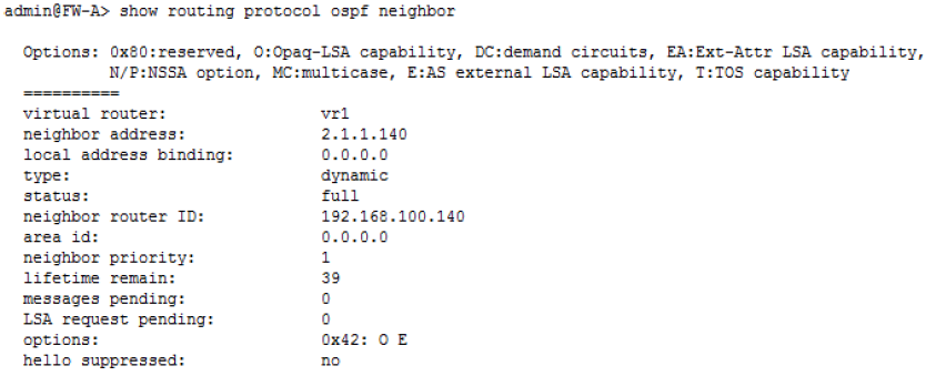
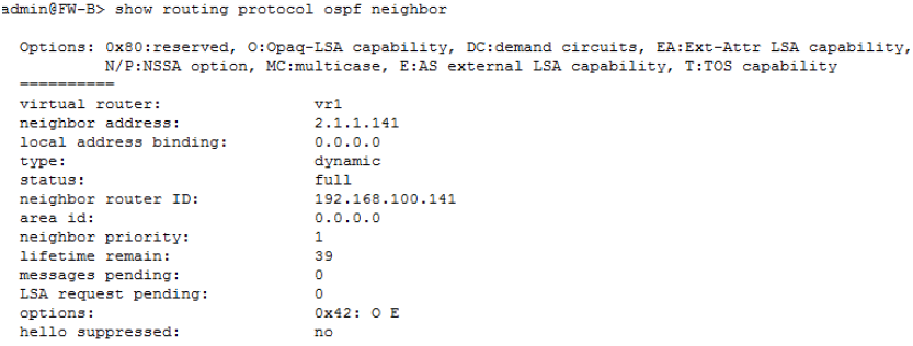
- Verify OSPF adjacencies and routes from the CLI.Verify that both the firewalls can see each other as neighbors with full status. Also confirm that the IP address of the VPN peer’s tunnel interface and the OSPF Router ID. Use the following CLI commands on each VPN peer.
- show routing protocol ospf neighbor

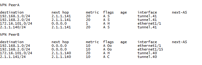
- show routing route
The following is an example of the output on each VPN peer.