Configure Active/Passive HA on AWS Using a Secondary IP
Table of Contents
Configure Active/Passive HA on AWS Using a Secondary IP
Deploy VM-Series firewall as HA pair with a secondary IP address.
Complete the following procedure to deploy
new VM-Series firewalls as an HA pair with secondary IP addresses.
All VM-Series firewall interfaces must be assigned an
IPv4 address when deployed in a public cloud environment.
- Before you deploy the VM-Series firewalls for you HA pair, ensure the following:
- Refer to the VPC Planning Worksheet to ensure that your VPC is prepared for the VM-Series firewall.
- Secondary IP Move HA requires VM-Series plugin 2.0.1 or later.
- Deploy both HA peers in the same AWS availability zone.Starting with VM-Series plugin 2.0.3, you can deploy the HA peers in different availability zones. Although this type of deployment is not recommended, it is supported.
- Create an IAM role and assign the role to the VM-Series firewalls when you deploy the instances.
- The active and passive firewalls must have at least four interfaces each—a management interface, an HA2 interface, an untrust interface, and a trust interface. Additionally, the trust and untrust interfaces on the active firewall must assigned a secondary IP address.The management interface must be used as the HA1 interface.
- Verify that the network and security components are defined suitably.
- Enable communication to the internet from the management interface (at least udp/53 and tcp/443). The default VPC includes an internet gateway, and if you install the VM-Series firewall in the default subnet it has access to the internet.
- Create subnets. Subnets are segments of the IP address range assigned to the VPC in which you can launch the EC2 instances. The VM-Series firewall must belong to the public subnet so that it can be configured to access the internet.
- Create a data security group that includes the firewall data interfaces. Additionally, configure the security to allow all traffic (0.0.0.0/0), so security is enforced by the firewalls. This is required to maintain existing sessions during failover.
- Add routes to the route table for a private subnet to ensure that traffic can be routed across subnets and security groups in the VPC, as applicable.
- If you are bootstrapping the firewall, create the necessary S3 bucket containing the required bootstrap files.
Deploy the VM-Series Firewall on AWS.- If your VM-Series firewalls do not have the VM-Series plugin 2.0.1 or later installed, upgrade the plugin before continuing.Configure ethernet 1/1 as the HA2 interface on each HA peer.
- Open the Amazon EC2 console.
- Select Network Interface and then choose then select your network interface.
- Select
- Leave the field blank to allow AWS to assign an IP address dynamically or enter an IP address within the subnet range for the VM-Series firewall.
- Click Yes and Update.
- Select and select Disable.
- Repeat this process on the second (to be passive) HA peer.
Add a secondary IP address to your dataplane interfaces on the first (to be active) HA peer.- Select Network Interface and then choose then select your network interface.
- Select .
- Leave the field blank to allow AWS to assign an IP address dynamically or enter an IP address within the subnet range for the VM-Series firewall.
- Click Yes and Update.
Associate an Elastic (public) IP address on the primary instance with the untrust interface of the active peer.- Select Elastic IPs and then choose the Elastic IP address to associate.
- Select .
- Under Resource Type, select Network Interface.
- Chose the network interface with which to associate the Elastic IP address.
- Click Associate.
For outbound traffic inspection, add an entry to the subnet route table that sets the next hop as the firewall trust interface.- Select .
- Choose your subnet route table.
- Select .
- Enter the Destination CIDR Block or IP address.
- For Target, enter the network interface of the firewall trust interface.
- Click Save routes.
To use AWS Ingress Routing, create a route table and associate the internet gateway to it. Then add an entry with the next hop set as the active firewall untrust interface.- Select .
- (Optional) Enter a descriptive Name tag for your route table.
- Click Create.
- Click your route table and select .
- Select Internet gateways and choose your VPC internet gateway.
- Click Save.
- Click your route table and select .
- For the Target, select Network Interface and choose the untrust interface of the active firewall.
- Click Save routes.
Configure the interfaces on the firewall. You must configure the HA2 data link and at least two Layer 3 interfaces for your untrust and trust interfaces. Complete this workflow on the first HA peer and then repeat the steps on the second HA peer.- Log in to the firewall web interface.Select and click on your untrust interface. In this example, the HA2 interface is 1/1, the trust interface is ethernet 1/2, and the untrust interface is ethernet 1/3.Click the link for ethernet 1/1 and configure as follows:
- Interface Type: HA
Click the link for ethernet 1/2 and configure as follows:- Interface Type: Layer3
- On the Config tab, assign the interface to the default router.
- On the Config tab, expand the Security Zone drop-down and select New Zone. Define a new zone, for example trust-zone, and then click OK.
- On the IPv4 tab, select DHCP Client.
- Check Enable.
- On the untrust interface, check Automatically create default route pointing to default gateway provided by server. This option tells the firewall to create a static route to a default gateway.
- Repeat these steps for ethernet 1/3.
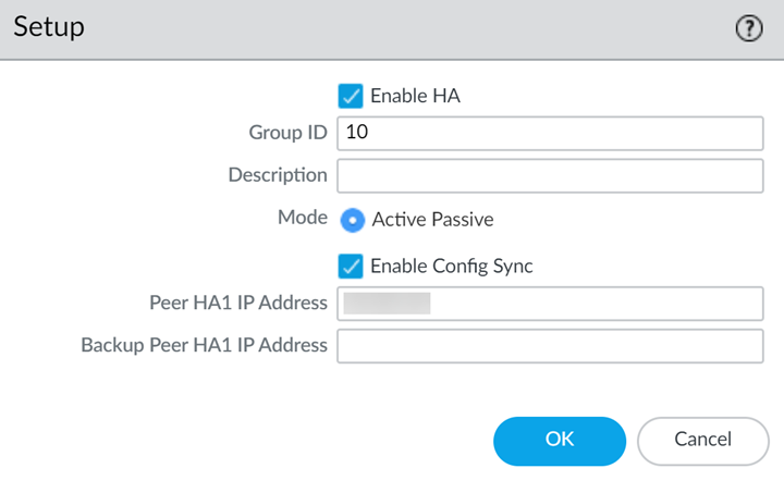
Repeat the above steps on the passive peer.Enable HA.- Select .Edit the Setup settings.Enter the private IP address of the passive peer in the Peer HA1 IP address field.Click OK.
![]() Edit the Election Settings to specify a particular firewall to be the active peer. Enter a lower numerical Device Priority value on the active firewall. If both firewalls have the same Device Priority value, the firewall with the lowest MAC value on the HA1 control becomes the active firewall.Enabling preemption is not recommended.Click OK.Commit your changes.Repeat the above steps on the passive peer.Set up the Control Link (HA1) to use the management port.
Edit the Election Settings to specify a particular firewall to be the active peer. Enter a lower numerical Device Priority value on the active firewall. If both firewalls have the same Device Priority value, the firewall with the lowest MAC value on the HA1 control becomes the active firewall.Enabling preemption is not recommended.Click OK.Commit your changes.Repeat the above steps on the passive peer.Set up the Control Link (HA1) to use the management port.- Select , and edit the Control Link (HA1) section.
![]() (Optional) Select Encryption Enabled, for secure HA communication between the peers. To enable encryption, you must export the HA key from a device and import it into the peer device.
(Optional) Select Encryption Enabled, for secure HA communication between the peers. To enable encryption, you must export the HA key from a device and import it into the peer device.- Select .
- Select Export HA key. Save the HA key to a network location that the peer device can access.
- On the peer device, navigate to , and select Import HA key to browse to the location that you saved the key and import it in to the peer device.
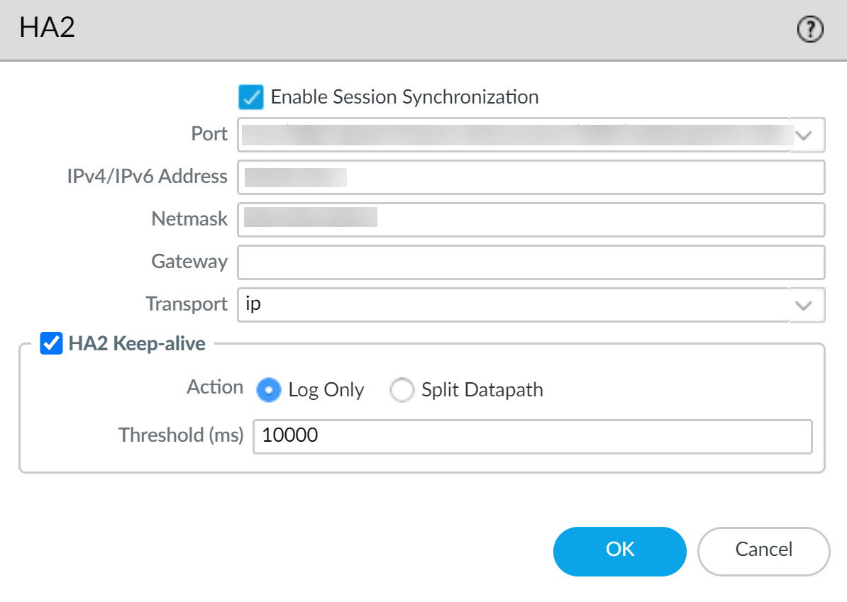
Set up the Data Link (HA2) to use ethernet1/1.- Select , edit the Data Link (HA2) section.Select Port ethernet1/1.Enter the IP address for ethernet1/1. This IP address must be the same that assigned to the ENI on the EC2 Dashboard.Enter the Netmask.Enter a Gateway IP address if the HA1 interfaces are on separate subnets.Select IP or UDP for Transport. Use IP if you need Layer 3 transport (IP protocol number 99). Use UDP if you want the firewall to calculate the checksum on the entire packet rather than just the header, as in the IP option (UDP port 29281).
![]() (Optional) Modify the Threshold for HA2 Keep-alive packets. By default, HA2 Keep-alive is enabled for monitoring the HA2 data link between the peers. If a failure occurs and this threshold (default is 10000 ms) is exceeded, the defined action will occur. A critical system log message is generated when an HA2 keep-alive failure occurs.You can configure the HA2 keep-alive option on both devices, or just one device in the HA pair. If you enable this option on one device, only that device will send the keep-alive messages.After your finish configuring HA on both firewalls, verify that the firewalls are paired in active/passive HA.
(Optional) Modify the Threshold for HA2 Keep-alive packets. By default, HA2 Keep-alive is enabled for monitoring the HA2 data link between the peers. If a failure occurs and this threshold (default is 10000 ms) is exceeded, the defined action will occur. A critical system log message is generated when an HA2 keep-alive failure occurs.You can configure the HA2 keep-alive option on both devices, or just one device in the HA pair. If you enable this option on one device, only that device will send the keep-alive messages.After your finish configuring HA on both firewalls, verify that the firewalls are paired in active/passive HA.- Access the Dashboard on both firewalls and view the High Availability widget.On the active HA peer, click Sync to peer.Confirm that the firewalls are paired and synced.
- On the passive firewall: the state of the local firewall should display Passive and the Running Config should show as Synchronized.
- On the active firewall: the state of the local firewall should display Active and the Running Config should show as Synchronized.
From the firewall command line interface, execute the following commands:- To verify failover readiness:show plugins vm_series aws ha state
- To show secondary IP mapping:show plugins vm_series aws ha ips