Enable Overlay Routing for the VM-Series on AWS
Table of Contents
Enable Overlay Routing for the VM-Series on AWS
Overly routing requires PAN-OS 10.0.5
or later.
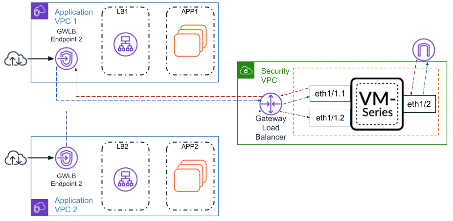
Using overlay routing in your VM-Series firewall
integration the AWS GWLB allows you to use two-zone policy to inspect
traffic leaving (egressing) your AWS environment. This allows packets
to leave the VM-Series firewall through a different interface than that
which they entered through.
When overlay routing is configured,
the firewall is able to perform a Layer 3 route lookup a packet’s
inner header. If the destination is the same as the ingress interface, the
packet will be directed as normal. All future packets in the session
are treated as vwire; as if overlay routing was not enabled. If
the packet is going to an outbound destination, the firewall decapsulates
the packet and forwards the packet to the IGW or NAT gateway. When
the packet returns, the firewall reapplies the encapsulation.
Use
the following procedure to enable overlay routing.
- Before you begin, ensure that you create different subnets for the trust and untrust interfaces.Manually Integrate the VM-Series with a Gateway Load Balancer.(Optional) Associate a VPC Endpoint with a VM-Series Interface.Use overlay routing CLI command. This CLI command is not required if you included the overlay routing op-command in the AWS user-data or the init-cfg.txt bootstrap file.
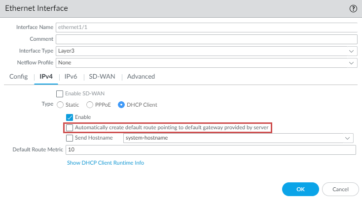
- Log in to the firewall command line interface.Execute the following command.request plugins vm_series aws gwlb overlay-routing enable yesLog in to the firewall web interface.Disable Automatically create default route pointing to default gateway provided by server on the trust (ingress) interface.
- Select .Click on your trust interface and then the IPv4 tab.Uncheck Automatically create default route pointing to default gateway provided by server.Click OK.
![]() Configure interface Ethernet 1/2.
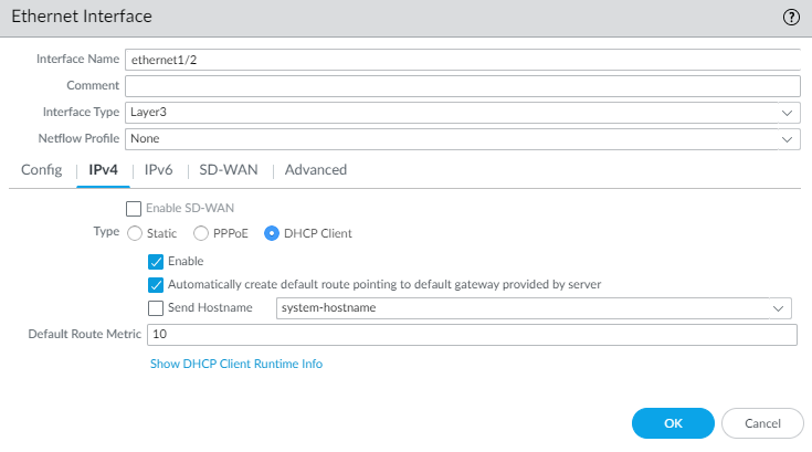
Configure interface Ethernet 1/2.- Select .Select the Interface Type—Layer 3.On the Config tab, expand the Security Zone drop-down and select New Zone. This zone will act as your untrust zone and directing outbound traffic out of your security VPC. Define the new zone, such as VM-Series-untrust, and then click OK.On the IPv4 tab, select DHCP Client.Select Automatically create default route pointing to default gateway provided by server.Click OK.
![]() Configure a virtual router.
Configure a virtual router.- Select .Enter a descriptive Name for the virtual router.Under Interfaces, Add Ethernet1/1, any subinterfaces under Ethernet1/1, and Ethernet1/2.Click .
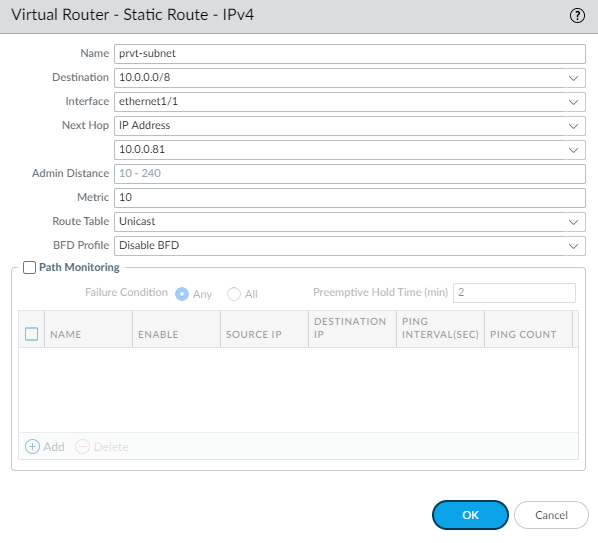
- Enter a descriptive name for the static route.
- As the Destination, enter the private IP address of the application VPC subnet.
- Select the trust (ingress) interface from the Interface drop-down.
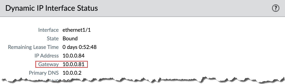
- For Next Hop, select IP Address and enter the IP address of the gateway of the trust interface. You can find the gateway IP address on .
![]()
- Click OK.
![]()
Ensure that the static routes can reach all application VPC in your deployment. You can either make a few large aggregated routes (covering all RFC1918) or application VPC specific routes. If you use subinterfaces, you do not need to route back to the sub-interface. The egress check looks only for the matching interface instead of the matching subinterface.Click OK.Create a NAT policy for traffic egressing Ethernet1/2.- Select .Enter a descriptive Name for the NAT policy rule.Select ipv4 from the NAT Type drop-down.On the Original Packet tab, set the Source Zone to any and the Destination Zone to your untrust (egress) zone.On the Translated Packet tab, set the following parameters.
- Translation Type: Dynamic IP and Port
- Address Type: Interface Address
- Interface: Select your untrust (egress) port from the drop-down.
- IP Address: None
Click OK.Commit your changes.