Configure Active/Passive HA on OCI
Table of Contents
Configure Active/Passive HA on OCI
You can configure a pair of VM-Series firewalls
on OCI in an active/passive high availability (HA)
configuration. To ensure uptime in an HA setup on OCI, you must
create a secondary, floating IP addresses that can quickly move
from one peer to the other. When the active firewall goes down,
the floating IP address moves from the active to the passive firewall
so that the passive firewall can seamlessly secure traffic as soon
as it becomes the active peer. In addition to the floating IP address,
the HA peers also need HA links—a control link
(HA1) and a data link (HA2)—to synchronize data and maintain state
information.
The VM-Series firewall for OCI in FIPS mode on PAN-OS version 10.2 and above
supports high availability.
To
allow the firewalls to move the floating IP address upon failover,
you must place the firewall instances in a dynamic group on OCI.
Dynamic groups allow you to group the firewall instances as principal
actors and create policy to allow the instances in the dynamic group
to make API calls against OCI services. You will use matching rules
to add the HA peer instances to the dynamic group and then create
the policy the floating IP from one VNIC to another.
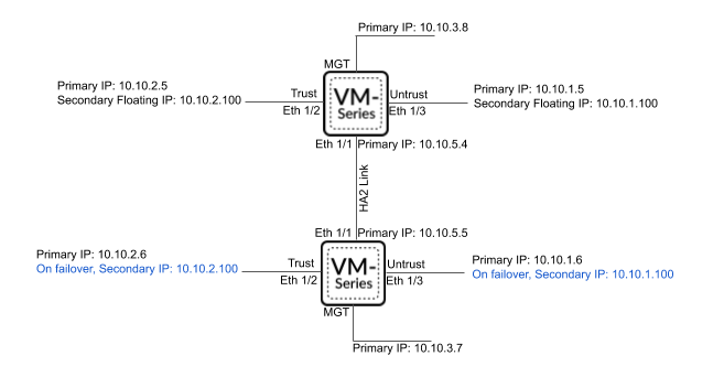
Both
VM-Series firewalls in the HA pair must have the same number of
network interfaces. Each firewall requires a minimum of four interfaces—management,
untrust, trust, and HA. You can configure additional data interfaces
as required by your deployment.
- Management interface—the private and public IP addresses associated with the primary interface. You can use the private IP address on the management interface as the IP address for the HA1 interface between the peers. If you want a dedicated HA interface, you must attach an additional interface to each firewall, for a total of five interfaces each.
- Untrust and trust interfaces—each of these data interfaces on the active HA peer require a primary and secondary IP address. Upon failover, when the passive HA peer transitions to the active state, the secondary private IP address is detached from the previously active peer and attached to the now active HA peer.
- HA2 interface—this interface has a single private IP address on each HA peer. The HA2 interface is the data link peers use to synchronize sessions, forwarding tables, IPsec security associations, and ARP tables.
- Deploy the VM-Series Firewall From the Oracle Cloud Marketplace and set up the network interfaces for HA.
- (Optional) Configure a dedicated HA1 interface on each HA peer.
- From the OCI Console, select and click on the name of your active peer instance.
- Select Attached VNICs and click Create VNIC.
- Enter a descriptive name for your HA1 interface.
- Select the VCN and subnet.
- Enter a private IP address.
- Click Create VNIC.
- Repeat this process on your passive peer instance.
Configure an HA2 interface on each HA peer.- From the OCI Console, select and click on the name of your active peer instance.
- Select Attached VNICs and click Create VNIC.
- Enter a descriptive name for your HA2 interface.
- Select the VCN and subnet. The HA2 interface should be on a separate subnet from your data interfaces.
- Enter a private IP address.
- Click Create VNIC.
- Repeat this process on your passive peer instance.
Add a secondary IP address to your dataplane interfaces on the active peer.- From the OCI Console, select and click on the name of your active peer instance.
- Select Attached VNICs and click on your untrust VNIC.
- Select IP Addresses and click Assign Private IP Address.
- Enter the IP address and click Assign.
- Repeat this procedure for each dataplane interface on your active peer.
Create security rules to allow the HA peers to synchronize data and maintain state information. By default, OCI allows ICMP traffic only. You must open the necessary HA ports.- Open the ports for your HA1 interface.
- From the OCI Console, select and select your VCN.
- Select Subnets and select the subnet containing your HA1 interface.
- Select Security Lists and click the default security list to edit it.
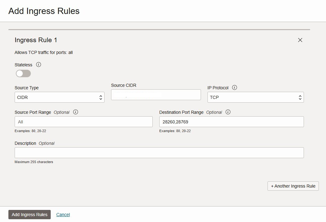
- Click Add Ingress Rule.
- Enter the Source CIDR that includes the HA peer HA1 port IP address.
- Select TCP from the IP Protocol drop-down.
- Click +Additional Ingress Rule.
![]() You need to create two additional rules for TCP ports 28260 and 28769 as the Destination Port Range.
You need to create two additional rules for TCP ports 28260 and 28769 as the Destination Port Range.![]()
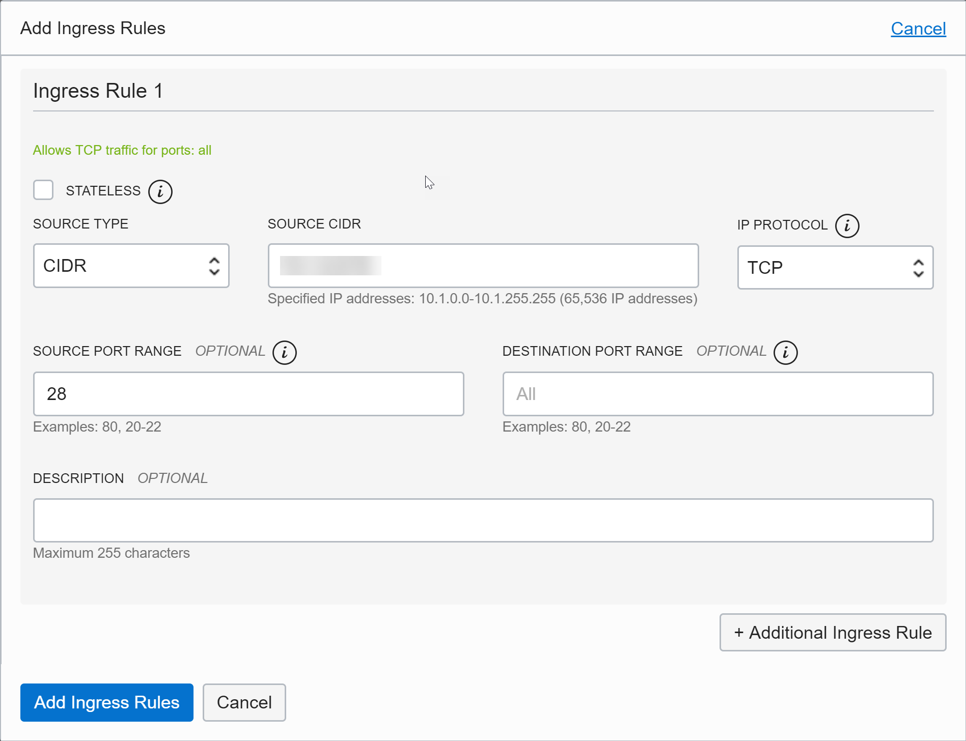
- If encryption is enabled on your VM-Series firewall for the HA1 link, create an additional rules for ICMP and TCP port 28.
- Click Add Ingress Rules.
![]() Open the ports for your HA2 interface.
Open the ports for your HA2 interface.- From the OCI Console, select and select your VCN.
- Select Subnets and select the subnet containing your HA2 interface.
- Select Security Lists and click the default security list to edit it.
- Click Add Ingress Rule.
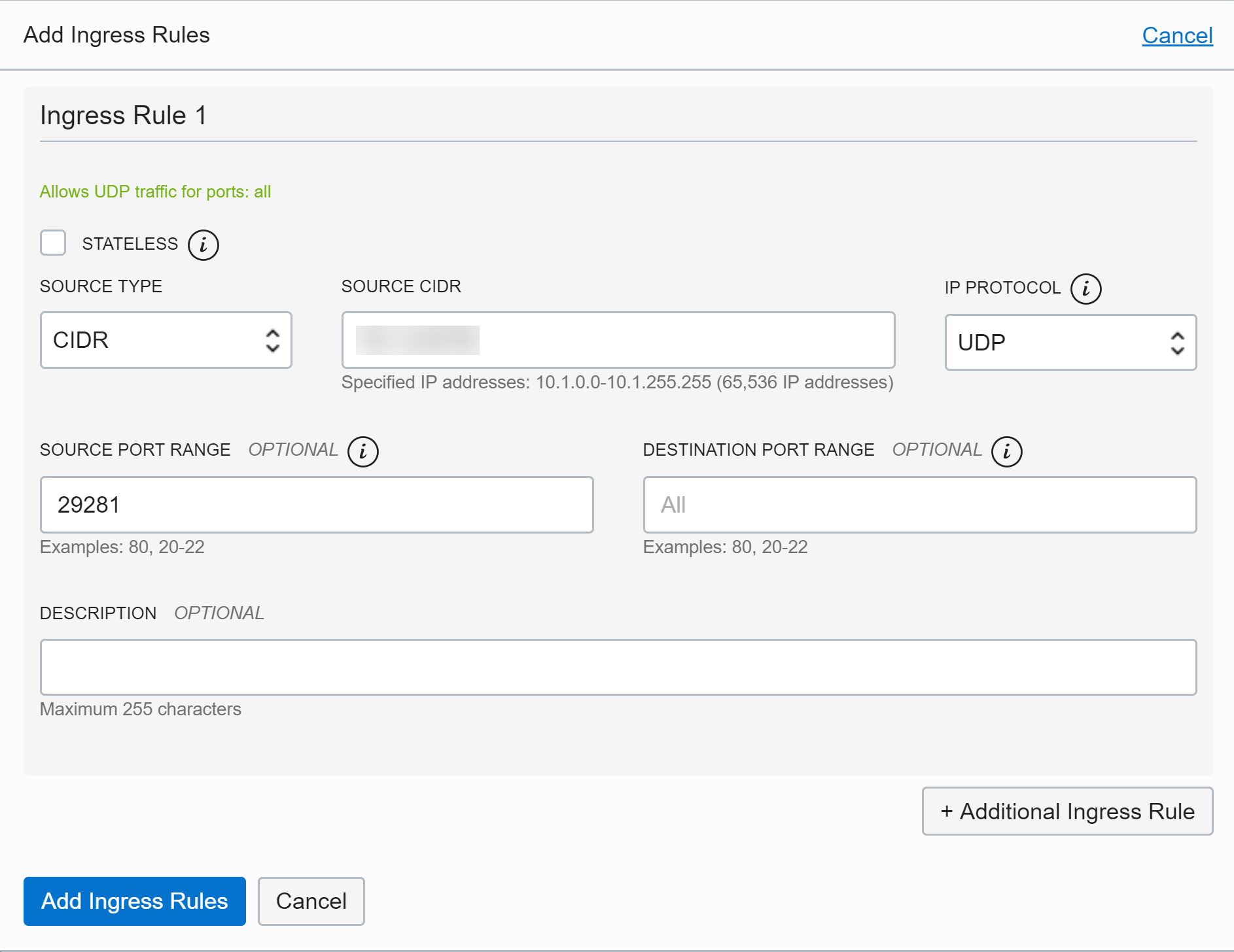
- Enter the Source CIDR that includes the HA peer HA2 port IP address.
- Select UDP or IP from the IP Protocol drop-down.
- If the transport mode is UDP, enter 29281 into Source Port Range. If the transport mode is IP, enter 99 into Source Port Range.
- Click Add Ingress Rules.
![]() Add both HA peers to a dynamic group and create policy that allows the HA peers to move the floating IP address. You must have the OCID of each HA peer instance to build the dynamic group matching rules, so have those on hand to past into the rule builder.
Add both HA peers to a dynamic group and create policy that allows the HA peers to move the floating IP address. You must have the OCID of each HA peer instance to build the dynamic group matching rules, so have those on hand to past into the rule builder.- Create the dynamic group.
- From the OCI Console, select .
- Enter a descriptive Name for your dynamic group.
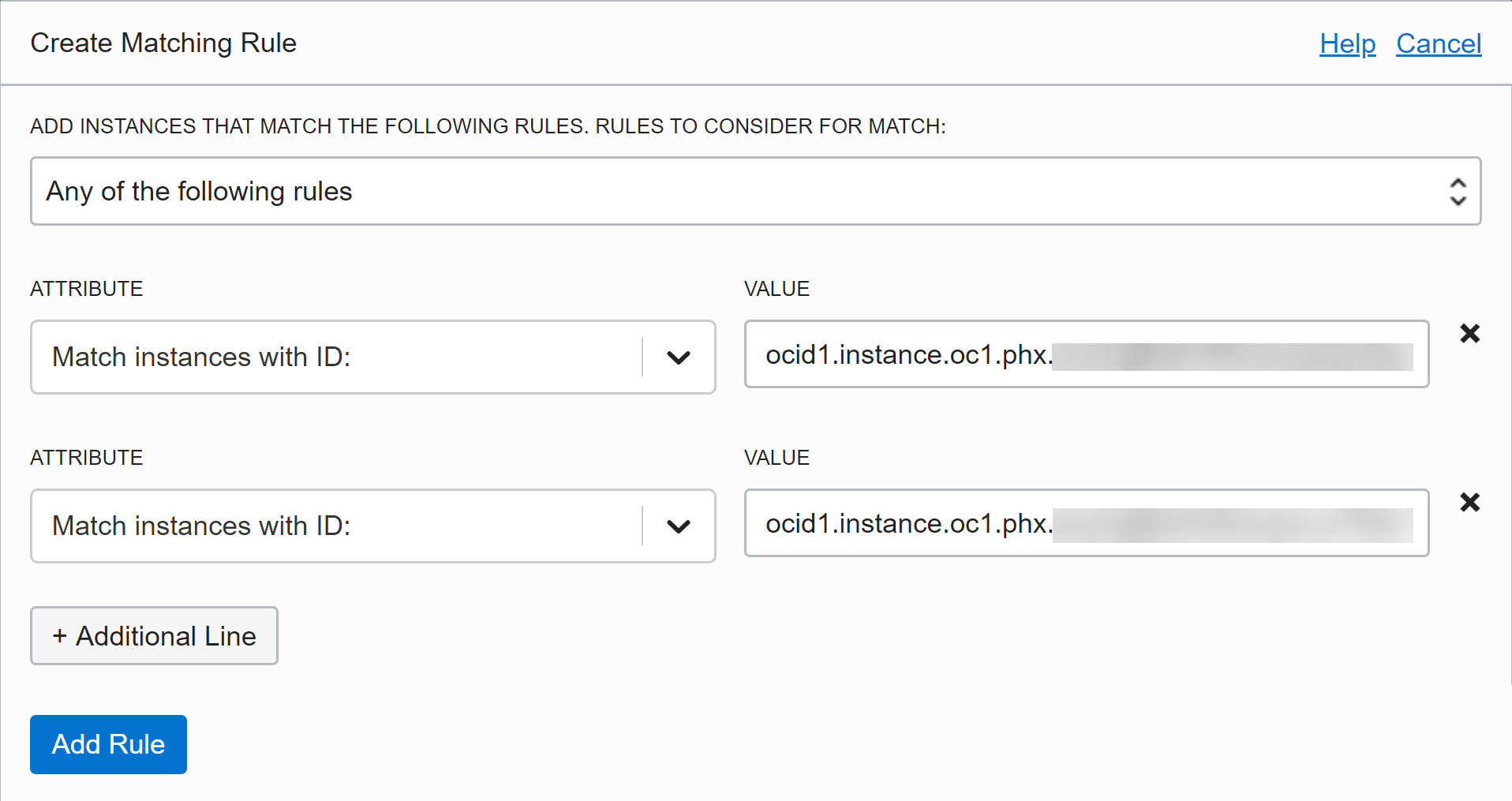
- Click Rule Builder.
- Select Any of the following rules from the first drop-down.
- Select Match instances with ID: from the Attributes drop-down and paste one of the peer OCIDs into the Value field.
- Click +Additional Line.
- Select Match instances with ID: from the Attributes drop-down and paste the other peer OCID into the Value field.
- Click Add Rule.
![]()
- Click Create Dynamic Group.
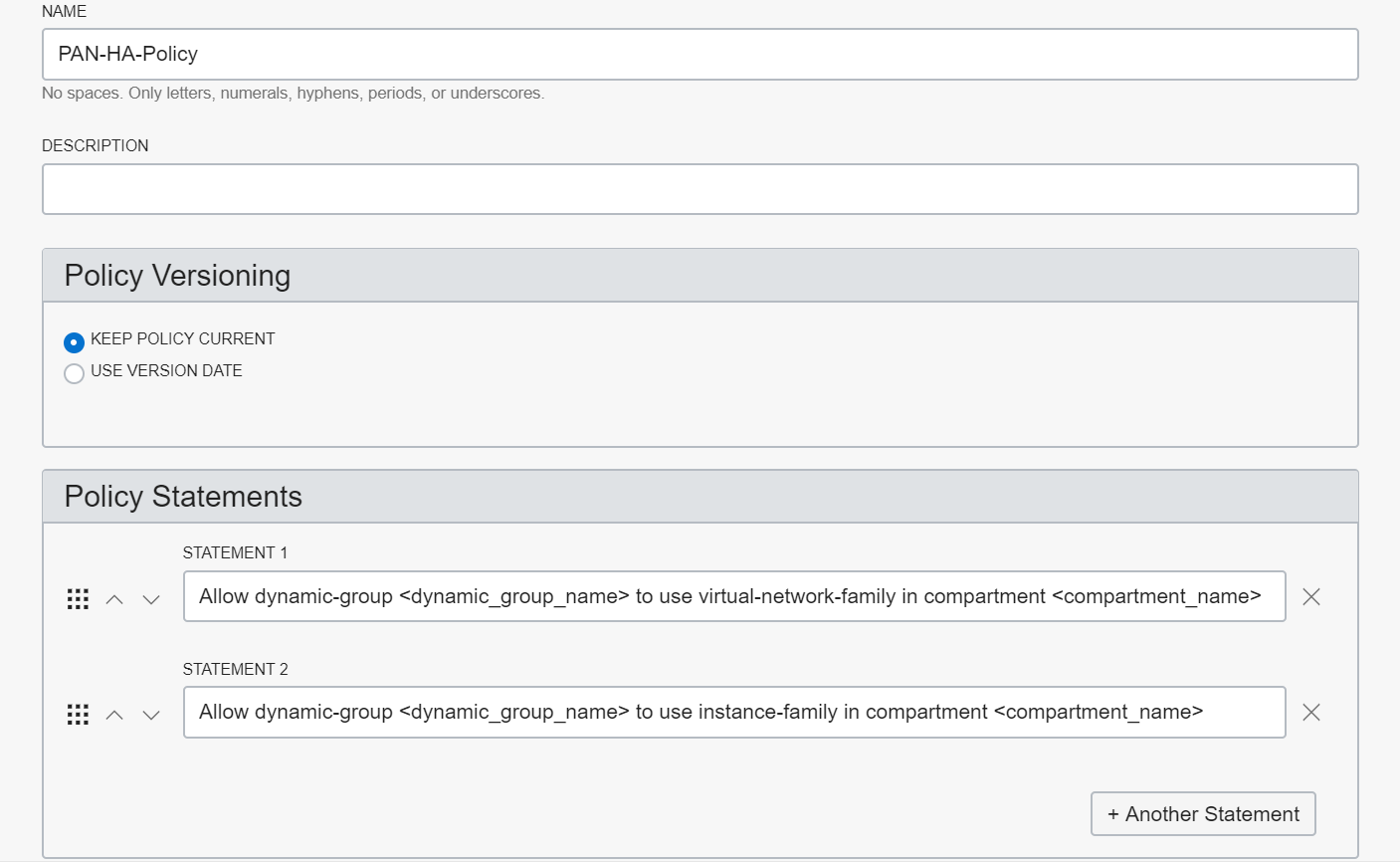
Create the policy rule.- From the OCI Console, select .
- Enter a descriptive Name for your policy.
- Enter the first policy statement.Allow dynamic-group <dynamic_group_name> to use virtual-network-family in compartment <compartment_name>
- Click +Another Statement.
- Enter the second policy statement.Allow dynamic-group <dynamic_group_name> to use instance-family in compartment <compartment_name>
- Click Create.
![]()
Configure the interfaces on the firewall. You must configure the HA2 data link and at least two Layer 3 interfaces for your untrust and trust interfaces. Complete this workflow on the first HA peer and then repeat the steps on the second HA peer.- Log in to the firewall web interface.(Optional) If you are using the management interface as HA1, you must set the interface IP Type to static and configure a DNS server.
- Select .
- Set the IP Type to Static.
- Enter the private IP address of the primary VNIC of your VM-Series firewall instance.
- Click OK.
- Select .
- Click Edit.
- Enter the IP address of the Primary DNS Server.
- Click OK.
- Commit your changes.
Select and click on your untrust interface. In this example, the HA2 interface is 1/1, the trust interface is ethernet 1/2, and the untrust interface is ethernet 1/3.Click the link for ethernet 1/1 and configure as follows:- Interface Type: HA
Click the link for ethernet 1/2 and configure as follows:- Interface Type: Layer3
- On the Config tab, assign the interface to the default router.
- On the Config tab, expand the Security Zone drop-down and select New Zone. Define a new zone, for example trust-zone, and then click OK.
- On the IPv4 tab, select either Static.
- Click Add in the IP section and enter the primary IP address and network mask for the interface. Make sure that the IP address matches the IP address that you assigned to the corresponding subnet in VCN. For example, if you add this interface to your trust zone, make sure you assign the trust vNIC IP address configured in your VCN.
- Click Add in the IP section and enter the secondary, floating IP address and network mask.
Click the link for ethernet 1/3 and configure as follows:- Interface Type: Layer3
- On the Config tab, assign the interface to the default router.
- On the Config tab, expand the Security Zone drop-down and select New Zone. Define a new zone, for example untrust-zone, and then click OK.
- On the IPv4 tab, select either Static.
- Click Add in the IP section and enter the primary IP address and network mask for the interface. Make sure that the IP address matches the IP address that you assigned to the corresponding subnet in VCN. For example, if you add this interface to your untrust zone, make sure you assign the untrust vNIC IP address configured in your VCN.
- Click Add in the IP section and enter the secondary, floating IP address and network mask.
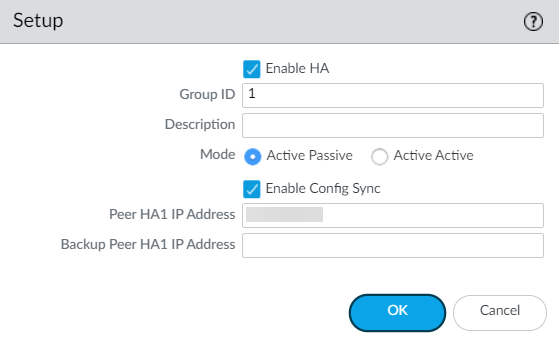
Enable HA.- Select .Edit the Setup settings.Enter the private IP address of the passive peer in the Peer HA1 IP address field.Click OK.
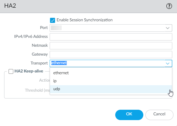
![]() (Optional) Edit the Control Link (HA1). If you do not plan to use the management interface for the control link and have added an additional interface (for example ethernet 1/4), edit this section to select the interface to use for HA1 communication.Edit the Data Link (HA2) to use Port ethernet 1/1 and add the IP address of active peer and the Gateway IP address for the subnet.Select IP or UDP from the Transport drop-down. Ethernet is not supported.
(Optional) Edit the Control Link (HA1). If you do not plan to use the management interface for the control link and have added an additional interface (for example ethernet 1/4), edit this section to select the interface to use for HA1 communication.Edit the Data Link (HA2) to use Port ethernet 1/1 and add the IP address of active peer and the Gateway IP address for the subnet.Select IP or UDP from the Transport drop-down. Ethernet is not supported.![]() Click OK.Commit your changes.Repeat step 4 and step 5 on the passive HA peer.After your finish configuring HA on both firewalls, verify that the firewalls are paired in active/passive HA.
Click OK.Commit your changes.Repeat step 4 and step 5 on the passive HA peer.After your finish configuring HA on both firewalls, verify that the firewalls are paired in active/passive HA.- Access the Dashboard on both firewalls and view the High Availability widget.On the active HA peer, click Sync to peer.Confirm that the firewalls are paired and synced.
- On the passive firewall: the state of the local firewall should display Passive and the Running Config should show as Synchronized.
- On the active firewall: the state of the local firewall should display Active and the Running Config should show as Synchronized.