Use Case: Secure the EC2 Instances in the AWS Cloud
Table of Contents
Use Case: Secure the EC2 Instances in the AWS Cloud
In this example, the VPC is deployed in the
10.0.0.0/16 network with two /24 subnets: 10.0.0.0/24 and 10.0.1.0/24.
The VM-Series firewall will be launched in the 10.0.0.0/24 subnet to
which the internet gateway is attached. The 10.0.1.0/24 subnet is
a private subnet that will host the EC2 instances that need to be
secured by the VM-Series firewall; any server on this private subnet
uses NAT for a routable IP address (which is an Elastic IP address)
to access the internet. Use the Planning
Worksheet for the VM-Series in the AWS VPC to plan the design
within your VPC; recording the subnet ranges, network interfaces
and the associated IP addresses for the EC2 instances, and security
groups, will make the setup process easier and more efficient.
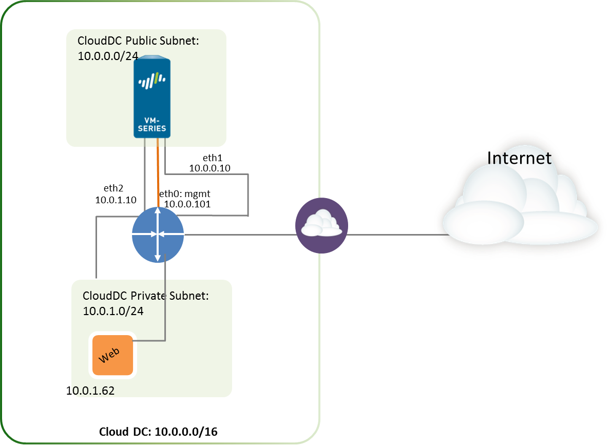
The following image depicts the logical flow of
traffic to/from the web server to the internet. Traffic to/from
the web server is sent to the data interface of the VM-Series firewall
that is attached to the private subnet. The firewall applies policy
and processes incoming/outgoing traffic from/to the internet gateway
of the VPC. The image also shows the security groups to which the
data interfaces are attached.

- Create a new VPC with a public subnet
(or select an existing VPC).
- Log in to the AWS console and select the VPC Dashboard.
- Verify that you’ve selected the correct geographic area (AWS region). The VPC will be deployed in the currently selected region.
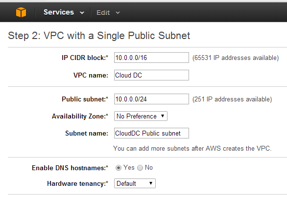
- Select Start VPC Wizard, and
select VPC with a Single Public Subnet.In this example, the IP CIDR block for the VPC is 10.0.0.0/16, the VPC name is Cloud DC, the public subnet is 10.0.0.0/24, and the subnet name is Cloud DC Public subnet. You will create a private subnet after creating the VPC.
![]()
- Click Create VPC.
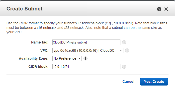
- Create a private subnet.Select Subnets, and click Create a Subnet. Fill in the information.In this example, the Name tag for the subnet is Web/DB Server Subnet, it is created in the Cloud Datacenter VPC and is assigned a CIDR block of 10.0.1.0/24.
![]()
- Create
a new route table for each subnet.Although a main route table is automatically created on the VPC, we recommend creating new route tables instead of modifying the default route table.To direct outbound traffic from each subnet, you will add routes to the route table associated with each subnet, later in this workflow.
- Select .
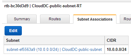
- Add a Name, for example CloudDC-public-subnet-RT, select the VPC you created in Step 1, and click Yes, Create.
- Select the route table, click Subnet Associations and
select the public subnet.
![]()
- Select Create Route Table.
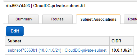
- Add a Name, for example CloudDC-private-subnet-RT, select the VPC you created in Step 1, and click Yes, Create.
- Select the route table, click Subnet Associations and
select the private subnet.
![]()
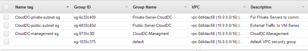
- Create Security Groups to restrict inbound/outbound internet
access to the EC2 instances in the VPC.By default, AWS disallows communication between interfaces that do not belong to the same security group.Select Security Groups and click the Create Security Group button. In this example, we create three security groups with the following rules for inbound access:
- CloudDC-Management that specifies the protocols and source IP addresses that can connect to the management interface of the VM-Series firewall. At a minimum you need SSH, and HTTPS. In this example, we enable SSH, ICMP, HTTP, and HTTPS on the network interfaces that are attached to this security group.The management interface (eth 0/0) of the VM-Series firewall will be assigned to CloudDC-management-sg.
- Public-Server-CloudDC that specifies the source IP addresses that can connect over HTTP, FTP, SSH within the VPC. This group allows traffic from the external network to the firewall.The dataplane interface eth1/1 of the VM-Series firewall will be assigned to Public-Server-CloudDC.
- Private-Server-CloudDC that has very limited access. It only allows other EC2 instances on the same subnet to communicate with each other, and with the VM-Series firewall.The dataplane interface eth1/2 of the VM-Series firewall and the application in the private subnet will be attached to this security group.The following screenshot shows the security groups for this use case.
![]()
- Deploy the VM-Series firewall.Only the primary network interface that will serve as the management interface will be attached and configured for the firewall during the initial launch. The network interfaces required for handling data traffic will be added in Step 6.
- Create
and attach virtual network interface(s), referred to as Elastic
Network Interfaces (ENIs), to the VM-Series firewall. These ENIs
are used for handling data traffic to/from the firewall.
- On the EC2 Dashboard, select Network Interfaces, and click Create Network Interface.
- Enter a descriptive name for the interface.
- Select the subnet. Use the subnet ID to make sure that you have selected the correct subnet. You can only attach an ENI to an instance in the same subnet.
- Enter the Private IP address that you want to assign to the interface or select Auto-assign to automatically assign an IP address within the available IP addresses in the selected subnet.
- Select the Security group to control access to the network interface.
- Click Yes, Create.In this example, we create two interfaces with the following configuration:
![]()
- For Eth1/1 (VM-Series-Untrust)
- Subnet: 10.0.0.0/24
- Private IP:10.0.0.10
- Security group: Public-Server-CloudDC
- For Eth1/2 (VM-Series-Trust)
- Subnet: 10.0.1.0/24
- Private IP: 10.0.1.10
- Security group: Private-Server-CloudDC
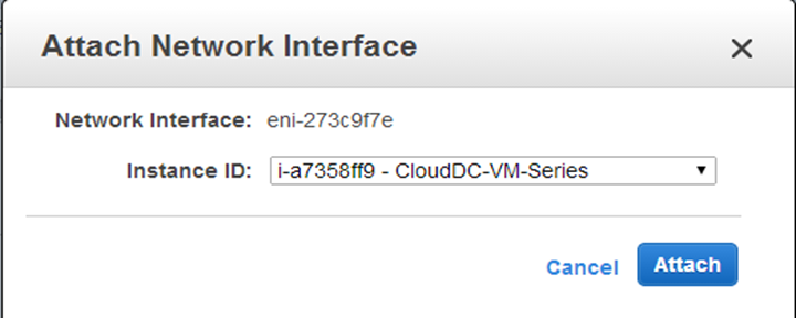
- To attach the ENI to the VM-Series firewall, select
the interface you just created, and click Attach.
![]()
- Select the Instance ID of the VM-Series firewall, and click Attach.
- Repeat steps 7 and 8 to attach the other network interface.
- Create an Elastic IP address and attach it to the firewall
dataplane network interface that requires direct internet access.In this example, VM-Series_Untrust is assigned an EIP. The EIP associated with the interface is the publicly accessible IP address for the web server in the private subnet.
- Select Elastic IPs and click Allocate New Address.
- Select EC2-VPC and click Yes, Allocate.
- Select the newly allocated EIP and click Associate Address.
- Select the Network Interface and
the Private IP address associated with the
interface and click Yes, Associate.
![]() In this example, the configuration is:
In this example, the configuration is:![]()
- Disable Source/Destination check on each network interface
attached to the VM-Series firewall. Disabling this attribute allows
the interface to handle network traffic that is not destined to
its IP address.
- Select the network interface in the Network Interfaces tab.
- In the Action drop-down, select Change Source/Dest. Check.
- Click Disabled and Save your changes.
- Repeat steps 1-3 for additional network interfaces, firewall-1/2 in this example.
- In the route table associated with the public subnet
(from step 3), add a default
route to the internet gateway for the VPC.
- From the VPC Dashboard, select Route Tables and find the route table associated with the public subnet.
- Select the route table, select Routes and click Edit.
- Add a route to forward packets from this subnet to
the internet gateway. In this example, 0.0.0.0.0 indicates that
all traffic from/to this subnet will use the internet gateway attached
to the VPC.
![]()
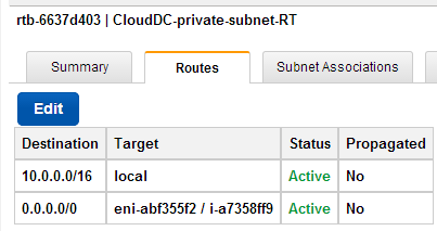
- In the route table associated with the private subnet,
add a default route to send traffic to the VM-Series firewall.Adding this route enables the forwarding of traffic from the EC2 instances in this private subnet to the VM-Series firewall.
- From the VPC Dashboard, select Route Tables and find the route table associated with the private subnet.
- Select the route table, select Routes and click Edit.
- Add a route to forward packets from this subnet to the VM-Series firewall network interface that resides on the same subnet. In this example, 0.0.0.0/0 indicates that all traffic from/to this subnet will use eni-abf355f2 (ethernet 1/2, which is CloudDC-VM-Series-Trust) on the VM-Series firewall.
- Configure
a new administrative password for the firewall.An SSH tool such as PuTTY is required to access the CLI on the firewall and change the default administrative password. You cannot access the web interface until you SSH and change the default password.
- Use the public IP address you configured
on the firewall, to SSH into the Command Line Interface (CLI) of
the VM-Series firewall.You will need the private key that you used or created in Launch the VM-Series Firewall on AWS, steps 3-12 to access the CLI.
- Enter the following command to log in to the firewall:ssh-i <private_key_name> admin@<public-ip_address>
- Configure a new password, using the following command
and follow the onscreen prompts:configureset mgt-config users admin passwordcommit
- Terminate the SSH session.
- Use the public IP address you configured
on the firewall, to SSH into the Command Line Interface (CLI) of
the VM-Series firewall.
- Access the web interface of the VM-Series firewall.Open a web browser and enter the EIP of the management interface. For example: https://54.183.85.163
- Activate the licenses on the VM-Series firewall. This
step is only required for the BYOL license; the usage-based licenses
are automatically activated.See Activate the License.
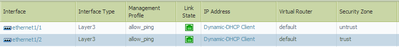
- On the
VM-Series firewall, configure the dataplane network interfaces on
the firewall as Layer 3 interfaces.
- Select .
- Click the link for ethernet 1/1 and
configure as follows:
- Interface Type: Layer3
- Select the Config tab, assign the interface to the default router.
- On the Config tab, expand the Security Zone drop-down and select New Zone. Define a new zone, for example untrust, and then click OK.
- Select IPv4, select DHCP Client; the private IP address that you assigned to the network interface in the AWS management console will be acquired automatically.
- On the tab, expand the Management Profile drop-down, and select New Management Profile.
- Enter a Name for the profile, such as allow_ping, and select Ping from the Permitted Services list, then click OK.
- To save the interface configuration, click OK.
- Click the link for ethernet 1/2 and
configure as follows:
- Interface Type: Layer3
- Select the Config tab, assign the interface to the default router.
- On the Config tab, expand the Security Zone drop-down and select New Zone. Define a new zone, for example trust, and then click OK.
- Select IPv4, select DHCP Client.
- On the IPv4 tab, clear the Automatically create default route to default gateway provided by server check box. For an interface that is attached to the private subnet in the VPC, disabling this option ensures that traffic handled by this interface does not flow directly to the IGW on the VPC.
- On the , expand the Management Profile drop-down, and select the allow_ping profile you created earlier.
- Click OK to save the interface configuration.
- Click Commit to save the changes.
Verify that the Link state for the interface is up . If the link state is not up, reboot the firewall.
![]()
![]()
- On the VM-Series firewall, create Destination NAT and
Source NAT rules to allow inbound/outbound traffic to/from the applications
deployed within the VPC.
- Select .
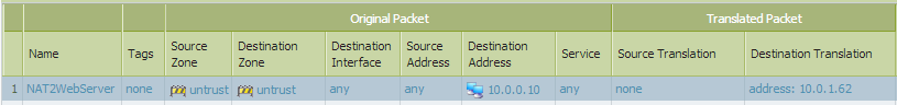
- Create a Destination NAT rule that steers traffic
from the firewall to the web server.
- Click Add, and enter a name for the rule. For example, NAT2WebServer.
- In the Original Packet tab, make the following selections:
- Source Zone: untrust (where the traffic originates)
- Destination Zone: untrust (the zone for the firewall dataplane interface with which the EIP for the web server is associated.)
- Source Address: Any
- Destination Address: 10.0.0.10
- In the Translated Packet tab, select the Destination Address Translation check box and set the Translated Address: to 10.0.1.62, which is the private IP address of the web server.
- Click OK.
![]()
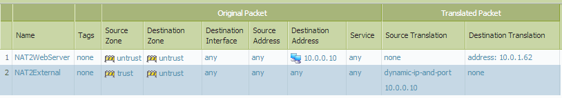
- Create a Source NAT rule to allow outbound traffic
from the web server to the internet.
- Click Add, and enter a name for the rule. For example, NAT2External.
- In the Original Packet tab, make the following selections:
- Source Zone: trust (where the traffic originates)
- Destination Zone: untrust (the zone for the firewall dataplane interface with which the EIP for the web server is associated.)
- Source Address: Any
- Destination Address: Any
- In the Translated Packet tab, make the following selections in the Source Address Translation section:
- Translation Type: Dynamic IP and Port
- Address Type: Translated Address
- Translated Address: 10.0.0.10 (the firewall dataplane interface in the untrust zone.)
- Click OK.
![]()
- Click Commit to save the NAT policies.
- On the
VM-Series firewall, create security policies to manage traffic.Instead of entering a static IP address for the web server, use a dynamic address group. Dynamic address groups allow you to create policy that automatically adapts to changes so that you do not need to update the policy when you launch additional web servers in the subnet. For details, see Use Case: Use Dynamic Address Groups to Secure New EC2 Instances within the VPC.
- Select .In this example, we have four rules. A rule that allows management access to the firewall traffic, a rule to allow inbound traffic to the web server, a third rule to allow internet access to the web server, and in the last rule we modify a predefined intrazone-default rule to log all traffic that is denied.
- Create a rule to allow management access to the firewall.
- Click Add and enter a Name for the rule. Verify that the Rule Type is universal.
- In the Source tab, add untrust as the Source Zone.
- In the Destination tab, add trust as the Destination Zone.
- In the Applications tab, Add ping and ssh.
- In the Actions tab, set the Action to Allow.
- Click OK.
![]()
- Create a rule to allow inbound traffic to the web
server.
- Click Add and enter a Name for the rule and verify that the Rule Type is universal.
- In the Source tab, add untrust as the Source Zone.
- In the Destination tab, add trust as the Destination Zone.
- In the Applications tab, Add web-browsing.
- In the Service/URL Category tab, verify that the service is set to application-default.
- In the Actions tab, set the Action to Allow.
- In the Profile Settings section of the Actions tab, select Profiles and then attach the default profiles for antivirus, anti-spyware, and vulnerability protection.
- Click OK.
![]()
- Create a rule to allow internet access to the web
server.
- Click Add and enter a Name for the rule and verify that the Rule Type is universal.
- In the Source tab, add trust as the Source Zone.
- In the Source Address section of the Source tab, add 10.0.1.62, the IP address of the web server.
- In the Destination tab, add untrust as the Destination Zone.
- In the Service/URL Category tab, verify that the service is set to application-default.
- In the Actions tab, set the Action to Allow.
- In the Profile Settings section of the Actions tab, select Profiles and then attach the default profiles for antivirus, anti-spyware, and vulnerability protection.
- Click OK.
![]()
- Edit the interzone-default rule to log all traffic
that is denied. This predefined interzone rule is evaluated when
no other rule is explicitly defined to match traffic across different
zones.
- Select the interzone-default rule and click Override.
- In the Actions tab, select Log at session end.
- Click OK.
![]()
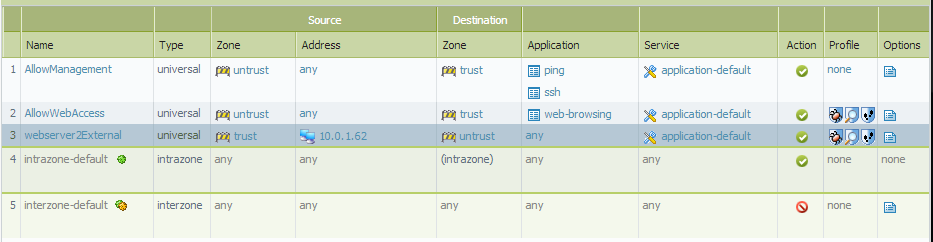
- Review the complete set of security rules defined on the firewall.
- Click Commit to save the policies.
![]()
- Select .
- Verify
that the VM-Series firewall is securing traffic.
- Launch a web browser and enter the IP address for the web server.
- Log in to the web interface of the VM-Series firewall
and verify that you can see the traffic logs for the sessions at .
- Traffic inbound to the web server (arrives at EC2 instance in the AWS VPC):
![]()
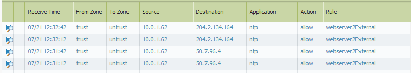
- Traffic outbound from the web server (EC2 instance in the AWS VPC):
![]()
You have successfully deployed the VM-Series firewall as a cloud gateway!