Install a PA-7500 Series Firewall Interface Card
Table of Contents
Expand all | Collapse all
Install a PA-7500 Series Firewall Interface Card
Learn how to install an MPC, NPC, DPC, and SFC in the chassis.
The Management Processing Card (MPC), Network Processing Card (NPC), and Data
Processing Card (DPC) are installed on the front panel of the chassis. The process
to install each of these interface cards is the same.
The following chassis front slots (numbered from top to bottom) can support the
following interface cards:
- 1—NPC and DPC
- 2—NPC and DPC
- 3—NPC and DPC
- 4—NPC and DPC
- 5—MPC (required)
- 6—NPC and DPC
- 7—NPC and DPC
- 8—NPC and DPC
- 9—NPC and DPC
Up to two Switch Fabric Cards (SFC) can be installed on the back of the chassis. The
process to install the SFC is similar to the other interface cards.
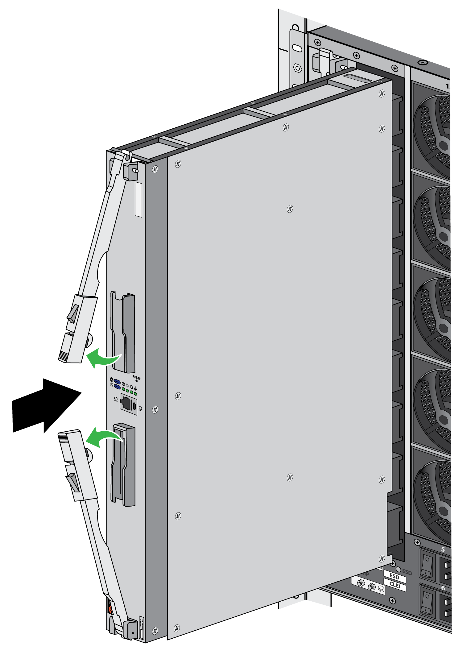
- Attach the provided ESD strap to your wrist and plug the other end in to the ESD port location on the appliance.Remove the interface card from the antistatic bag.The cards are heavy and should be removed and replaced in their antistatic bags on a table or other flat, stable surface. Ensure that the card connectors do not make contact with other surfaces or objects.(MPC, NPC, and DPC) Push the left and right ejector tabs towards each other to allow the ejector handles to rotate into an open position. Then gently push the interface card into the appropriate slot until the card reaches the end of the slot. Close the ejector handles to ensure that the card is secure in place.
![]() (SFC) Pull the ejector tabs away from the center and rotate the handles outwards. Then gently push the interface card into the appropriate slot until the card reaches the end of the slot. Close the ejector handles in unison; the card is secure in place when the latches are roughly parallel to the plastic guides that they are seated inside.
(SFC) Pull the ejector tabs away from the center and rotate the handles outwards. Then gently push the interface card into the appropriate slot until the card reaches the end of the slot. Close the ejector handles in unison; the card is secure in place when the latches are roughly parallel to the plastic guides that they are seated inside.![]()
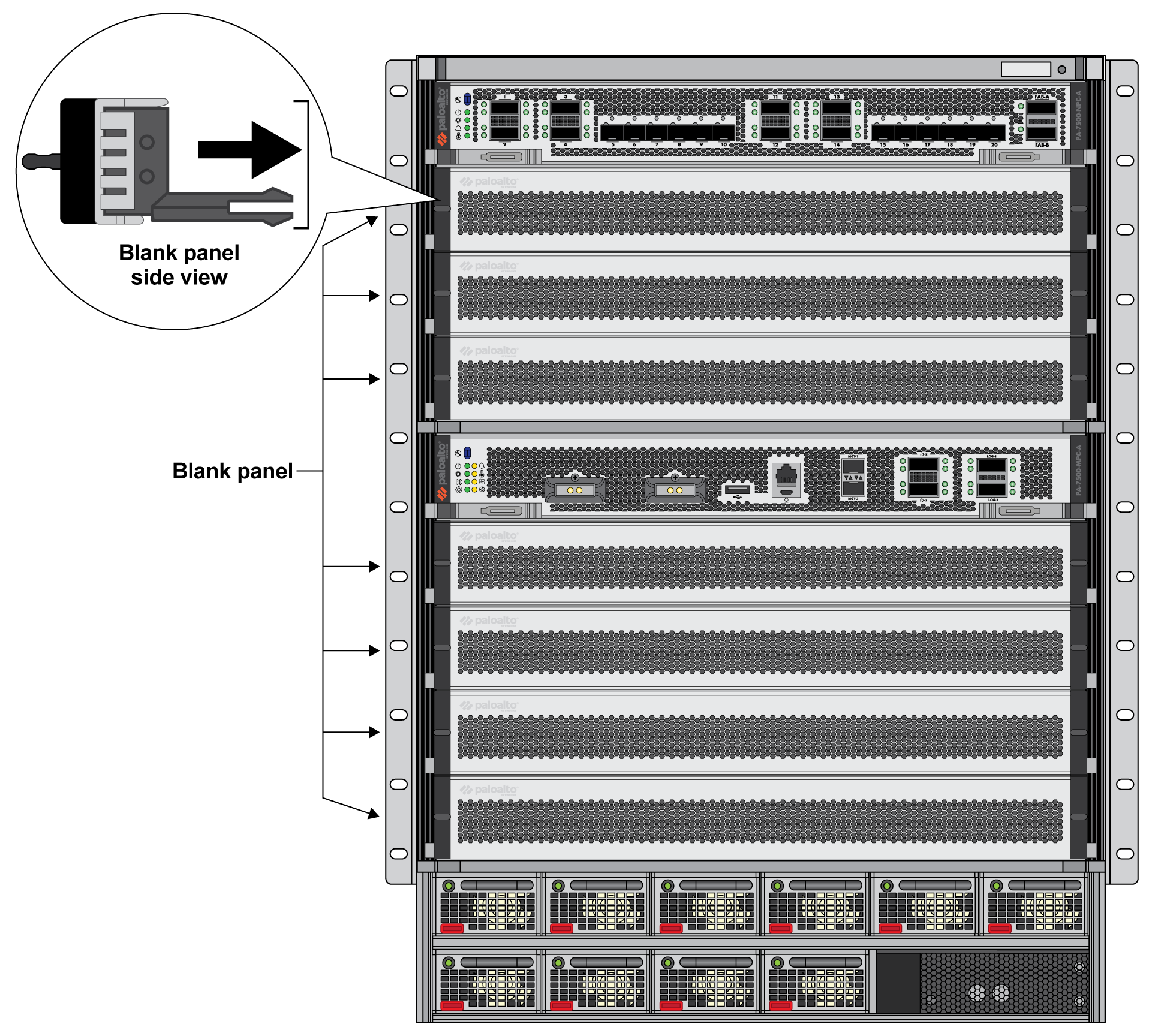
![]() Install blanks in all unused slots to help maintain chassis air flow.
Install blanks in all unused slots to help maintain chassis air flow.- (MPC, NPC, and DPC) Insert the blank into the front slot. Ensure that the two prongs on either side of the blank fit within the ridges on the inside of the chassis.
![]()
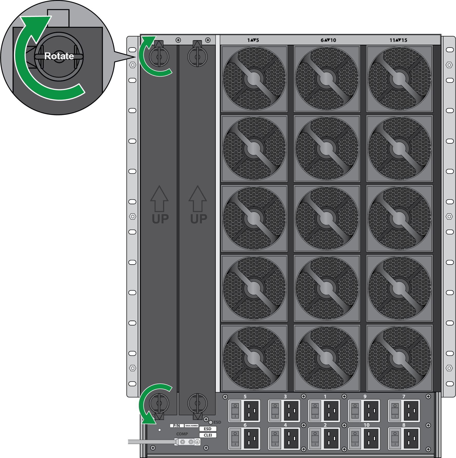
![]() To remove the blank, grip the two handles and pull it outwards. Some force may be necessary to remove the blank.(SFC) Insert the blank into the back slot. Secure the blank in place by turning the two thumb tabs so that they lock into the chassis.
To remove the blank, grip the two handles and pull it outwards. Some force may be necessary to remove the blank.(SFC) Insert the blank into the back slot. Secure the blank in place by turning the two thumb tabs so that they lock into the chassis.![]() To remove the blank, turn the thumb tabs so that it is unlocked from the chassis. Pull the blank outwards.
To remove the blank, turn the thumb tabs so that it is unlocked from the chassis. Pull the blank outwards.


