: PA-7500 Series Firewall MPC LEDs
Focus
Focus

PA-7500 Series Firewall MPC LEDs

Table of Contents

PA-7500 Series Firewall MPC LEDs

Learn how to interpret the LEDs located on the PA-7500 Series firewall Management Processing Card.
The following table describes how to interpret the status LEDs on a Management Processing Card (MPC).
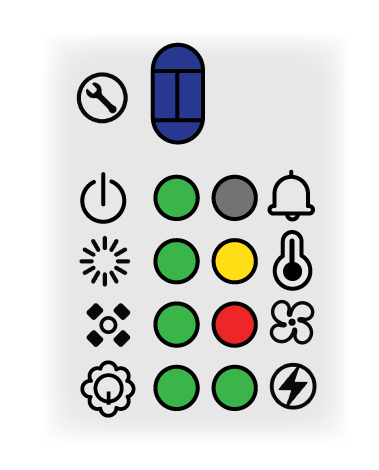
LEDDescription
Service
Allows a remote administrator to illuminate the LED on a specific front-slot card so an on-site technician can locate the card.
  • Off—The firewall is operating normally.
  • Blue—The firewall is instructed by the CLI or Web Interface to enable this LED.
Power
  • Green—The firewall is powered on.
  • Yellow—The firewall is shutting down or there is an issue with one or more power rails.
  • Off—The firewall is not powered on or an error occurred with the internal power system (for example, power is not within tolerance levels).
Status
  • Green—The firewall is operating normally.
  • Yellow—The firewall is booting.
High Availability
  • Green—The firewall is the active peer in an active/passive configuration.
  • Yellow—The firewall is the passive peer in an active/passive configuration.
  • Off—High availability (HA) is not operational on this firewall.
In an active/active configuration, the HA LED only indicates HA status for the local firewall and has two possible states (green or off); it does not indicate HA connectivity of the peer. Green indicates that the firewall is either active-primary or active-secondary and off indicates that the firewall is in any other state (For example, non-functional or suspended).
Active/Standby
  • Green—Active
  • Yellow—Standby
Alarm
  • Off—The firewall is operating normally.
  • Red—A hardware failure, such as a power supply failure, a firewall failure that caused an HA failover, a drive failure, or the hardware overheated and exceeded the high temperature threshold.
Temperature
  • Green—The firewall temperature is normal.
  • Yellow—The firewall temperature is outside tolerance levels.
See the PA-7500 Series Firewall Environmental Specifications for the operating temperature range.
Fans
  • Green—The fan tray and all fans are operating normally.
  • Red—A fan has failed.
Power Supplies
  • Green—The power supplies are operating normally.
  • Red—A power supply is present but is not working.
The following table describes how to interpret the LEDs on the MPC ports.
LEDDescription
LOG-1 and LOG-2 (QSFP28)
The QSFP28 ports have four LEDs each; the LED illuminated depends on the transceiver that is installed.
On the zQSFP ports, the left LED glows yellow when a 1Gbps transceiver is connected and the right LED glows green when a 10Gbps transceiver is connected. When operating at 25Gbps speed, the right LED glows teal.
The color of the LED differs based on the port speed.
  • 1Gbps—Yellow
  • 10Gbps—Green
  • 25Gbps—Teal
  • 40Gbps—Yellow
  • 100Gbps—Blue
  • Solid Color—The firewall network link is up.
  • Blinking Color—The firewall is processing network activity.
HSCI-A and HSCI-B (QSFP28)
The QSFP28 ports have four LEDs each.
On the QSFP28 ports, the LEDs are illuminated based on breakout status. Breaking out the port to 10Gbps causes all LEDs to glow green. Breaking out the port to 100Gbps causes all LEDs to glow teal. If the port is not broken out, the LEDs glow yellow for 40Gbps and blue for 400Gbps.