Prisma SD-WAN
Configure a Cellular Software Bypass Pair
Table of Contents
Expand All
|
Collapse All
Prisma SD-WAN Docs
-
-
-
- CloudBlade Integrations
- CloudBlades Integration with Prisma Access
-
-
-
-
- 6.5
- 6.4
- 6.3
- 6.2
- 6.1
- 5.6
- New Features Guide
- On-Premises Controller
- Prisma SD-WAN CloudBlades
- Prisma Access CloudBlade Cloud Managed
- Prisma Access CloudBlade Panorama Managed
Configure a Cellular Software Bypass Pair
Let us learn how to configure a cellular software bypass pair.
| Where Can I Use This? | What Do I Need? |
|---|---|
|
|
Software cellular bypass creates a software bridge between the ethernet and
cellular interfaces of an ION device. To support cellular WAN links in a high
availability (HA) configuration, configure a software cellular bypass pair with a
cellular link as one interface and an ethernet link as another interface. When both
the links are active, the active ION device employs a path selection algorithm to
select the best path.
In an HA topology, when the WAN link attached to the active device fails,
the active device can continue to route traffic over the WAN link attached to the
backup device. If one of the ION devices fails, the other device can take over
routing of the traffic between LANs and to/from the WANs.
- Select ConfigurationPrisma SD-WANION DevicesClaimed, select the device you want to configure.Select Interfaces.Select a port.On the Main Configuration > General settings, add Tags.For Admin Up, select Yes.When you create a bypass pair, both the ports are up. When you bring down the bypass pair, both ports will be set to down. After that you have to bring up the ports individually. For security reasons, bringing up the individual port of the bypass pair is necessary. Failing to do so, the individual ports of the bypass pair will remain down and may impact the software upgrade process.(Optional) Enter a Description.In Network Settings, enter the following information:
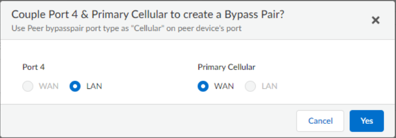
- Select Bypass Pair as the Interface TypeFor Use These Port For, select either Internet, or Private WAN.For Pair With, choose a pairing port to create a bypass pair and then click Done.Set one port as WAN and the second as LAN on the Couple Ports to create a Bypass Pair pop-up. For cellular bypass pairs, the cellular interface is always WAN and the peer is always LAN.
![]() Choose a Circuit Label.The circuit label for the cellular interface should match the circuit label for the peer device’s directly attached cellular interface.The IPv4 Configuration is auto-negotiated for the Cellular bypass.Select the Scope of the port.Select IPFIX Collector and IPFIX Filter for the port.Configure the Cellular WAN interface as an internet transit zone in the NAT Zone configuration.Configure the Advanced Settings by entering the following information:
Choose a Circuit Label.The circuit label for the cellular interface should match the circuit label for the peer device’s directly attached cellular interface.The IPv4 Configuration is auto-negotiated for the Cellular bypass.Select the Scope of the port.Select IPFIX Collector and IPFIX Filter for the port.Configure the Cellular WAN interface as an internet transit zone in the NAT Zone configuration.Configure the Advanced Settings by entering the following information:- Disable IoT SNMP Discovery Source InterfaceSecurity Group Info is disabled.Enter Host Name and MAC address.Enter External Nat Address (IPv4) and the Port (IPv4) number.Enter the IP MTU range. The range for IPv4 is 552 to 1500 and for IPv6 is 1280 to 1500.Select Physical settings.Save the bypass pair.
Configure WAN (Peer) Interfaces
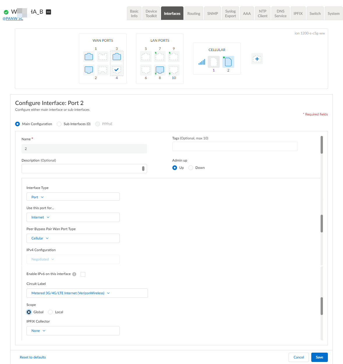
In an HA configuration, the initial step is to configure a cellular bypass pair and configure a WAN port on each ION device. The next step is to mirror the WAN configuration on the connected WAN port of the other ION device.The ION devices operate in an active/backup configuration, and through fail-to-wire functionality, the active ION device constantly maintains complete control and utilizes the full capacity of all the WAN circuits. As a result, you need to configure WAN circuits on both the ION devices.- Select ConfigurationPrisma SD-WANION DevicesClaimed, select the device you want to configure.Select Interfaces.Select a port.For Admin Up, select Yes.Select Internet or WAN for Use this ports for.Select Cellular in Peer Bypass Pair Wan Port Type to use the cellular bypass pair in a HA topology.This field is used in an HA environment to inherit cellular configuration on an Ethernet port using the peer bypass pair for the cellular traffic.When creating a Cellular 5G/LTE + Ethernet software bypass, the LAN interface in a bypass pair should be directly connected to the Ethernet port on the other ION device, which will terminate the VPNs built over the cellular circuit.Specify the APN profile for the Cellular interface.The IPv4 Configuration is auto-negotiated for the Cellular bypass.Choose a Circuit Label.Use the same circuit on the bypass pair. The circuit label for the cellular interface should match the circuit label for the peer spoke’s directly attached cellular interface.
![]() Save the configuration.
Save the configuration.


