Secure an AKS Cluster
Table of Contents
10.0 (EoL)
Expand all | Collapse all
-
- VM-Series Deployments
- VM-Series in High Availability
- Enable Jumbo Frames on the VM-Series Firewall
- Hypervisor Assigned MAC Addresses
- Custom PAN-OS Metrics Published for Monitoring
- Interface Used for Accessing External Services on the VM-Series Firewall
- PacketMMAP and DPDK Driver Support
- Enable ZRAM on the VM-Series Firewall
-
- VM-Series Firewall Licensing
- Create a Support Account
- Serial Number and CPU ID Format for the VM-Series Firewall
- Install a License API Key
- Use Panorama-Based Software Firewall License Management
-
- Maximum Limits Based on Memory
- Activate Credits
- Create a Deployment Profile
- Manage a Deployment Profile
- Register the VM-Series Firewall (Software NGFW Credits)
- Provision Panorama
- Migrate Panorama to a FW-Flex License
- Transfer Credits
- Renew Your Software NGFW Credit License
- Deactivate License (Software NGFW Credits)
- Create and Apply a Subscription-Only Auth Code
- Migrate to a Flexible VM-Series License
- What Happens When Licenses Expire?
-
- Supported Deployments on VMware vSphere Hypervisor (ESXi)
-
- Plan the Interfaces for the VM-Series for ESXi
- Provision the VM-Series Firewall on an ESXi Server
- Perform Initial Configuration on the VM-Series on ESXi
- Add Additional Disk Space to the VM-Series Firewall
- Use VMware Tools on the VM-Series Firewall on ESXi and vCloud Air
- Use vMotion to Move the VM-Series Firewall Between Hosts
- Use the VM-Series CLI to Swap the Management Interface on ESXi
-
-
- VM-Series Firewall for NSX-V Deployment Checklist
- Install the VMware NSX Plugin
- Apply Security Policies to the VM-Series Firewall
- Steer Traffic from Guests that are not Running VMware Tools
- Dynamically Quarantine Infected Guests
- Migrate Operations-Centric Configuration to Security-Centric Configuration
- Add a New Host to Your NSX-V Deployment
- Use Case: Shared Compute Infrastructure and Shared Security Policies
- Use Case: Shared Security Policies on Dedicated Compute Infrastructure
- Dynamic Address Groups—Information Relay from NSX-V Manager to Panorama
-
- Supported Deployments of the VM-Series Firewall on VMware NSX-T (North-South)
- Components of the VM-Series Firewall on NSX-T (North-South)
-
- Install the Panorama Plugin for VMware NSX
- Enable Communication Between NSX-T Manager and Panorama
- Create Template Stacks and Device Groups on Panorama
- Configure the Service Definition on Panorama
- Deploy the VM-Series Firewall
- Direct Traffic to the VM-Series Firewall
- Apply Security Policy to the VM-Series Firewall on NSX-T
- Use vMotion to Move the VM-Series Firewall Between Hosts
- Extend Security Policy from NSX-V to NSX-T
-
- Components of the VM-Series Firewall on NSX-T (East-West)
- VM-Series Firewall on NSX-T (East-West) Integration
- Supported Deployments of the VM-Series Firewall on VMware NSX-T (East-West)
-
- Install the Panorama Plugin for VMware NSX
- Enable Communication Between NSX-T Manager and Panorama
- Create Template Stacks and Device Groups on Panorama
- Configure the Service Definition on Panorama
- Launch the VM-Series Firewall on NSX-T (East-West)
- Add a Service Chain
- Direct Traffic to the VM-Series Firewall
- Apply Security Policies to the VM-Series Firewall on NSX-T (East-West)
- Use vMotion to Move the VM-Series Firewall Between Hosts
-
- Install the Panorama Plugin for VMware NSX
- Enable Communication Between NSX-T Manager and Panorama
- Create Template Stacks and Device Groups on Panorama
- Configure the Service Definition on Panorama
- Launch the VM-Series Firewall on NSX-T (East-West)
- Create Dynamic Address Groups
- Create Dynamic Address Group Membership Criteria
- Generate Steering Policy
- Generate Steering Rules
- Delete a Service Definition from Panorama
- Migrate from VM-Series on NSX-T Operation to Security Centric Deployment
- Extend Security Policy from NSX-V to NSX-T
- Use In-Place Migration to Move Your VM-Series from NSX-V to NSX-T
- Use Migration Coordinator to Move Your VM-Series from NSX-V to NSX-T
-
-
- Deployments Supported on AWS
-
- Planning Worksheet for the VM-Series in the AWS VPC
- Launch the VM-Series Firewall on AWS
- Launch the VM-Series Firewall on AWS Outpost
- Create a Custom Amazon Machine Image (AMI)
- Encrypt EBS Volume for the VM-Series Firewall on AWS
- Use the VM-Series Firewall CLI to Swap the Management Interface
- Enable CloudWatch Monitoring on the VM-Series Firewall
-
- Use Case: Secure the EC2 Instances in the AWS Cloud
- Use Case: Use Dynamic Address Groups to Secure New EC2 Instances within the VPC
-
-
- What Components Does the VM-Series Auto Scaling Template for AWS (v2.0) Leverage?
- How Does the VM-Series Auto Scaling Template for AWS (v2.0 and v2.1) Enable Dynamic Scaling?
- Plan the VM-Series Auto Scaling Template for AWS (v2.0 and v2.1)
- Customize the Firewall Template Before Launch (v2.0 and v2.1)
- Launch the VM-Series Auto Scaling Template for AWS (v2.0)
- SQS Messaging Between the Application Template and Firewall Template
- Stack Update with VM-Series Auto Scaling Template for AWS (v2.0)
- Modify Administrative Account and Update Stack (v2.0)
-
- Launch the Firewall Template (v2.1)
- Launch the Application Template (v2.1)
- Create a Custom Amazon Machine Image (v2.1)
- VM-Series Auto Scaling Template Cleanup (v2.1)
- SQS Messaging Between the Application Template and Firewall Template (v2.1)
- Stack Update with VM-Series Auto Scaling Template for AWS (v2.1)
- Modify Administrative Account (v2.1)
- Change Scaling Parameters and CloudWatch Metrics (v2.1)
-
-
- Enable the Use of a SCSI Controller
- Verify PCI-ID for Ordering of Network Interfaces on the VM-Series Firewall
-
- Deployments Supported on Azure
- Deploy the VM-Series Firewall from the Azure Marketplace (Solution Template)
- Deploy the VM-Series Firewall from the Azure China Marketplace (Solution Template)
- Create a Custom VM-Series Image for Azure
- Deploy the VM-Series Firewall on Azure Stack
- Enable Azure Application Insights on the VM-Series Firewall
- Set up Active/Passive HA on Azure
- Use the ARM Template to Deploy the VM-Series Firewall
-
- About the VM-Series Firewall on Google Cloud Platform
- Supported Deployments on Google Cloud Platform
- Prepare to Set Up VM-Series Firewalls on Google Public Cloud
- Create a Custom VM-Series Firewall Image for Google Cloud Platform
-
- Deploy the VM-Series Firewall from Google Cloud Platform Marketplace
- Management Interface Swap for Google Cloud Platform Load Balancing
- Use the VM-Series Firewall CLI to Swap the Management Interface
- Enable Google Stackdriver Monitoring on the VM Series Firewall
- Enable VM Monitoring to Track VM Changes on Google Cloud Platform (GCP)
- Use Dynamic Address Groups to Secure Instances Within the VPC
- Use Custom Templates or the gcloud CLI to Deploy the VM-Series Firewall
-
- Prepare Your ACI Environment for Integration
-
-
- Create a Virtual Router and Security Zone
- Configure the Network Interfaces
- Configure a Static Default Route
- Create Address Objects for the EPGs
- Create Security Policy Rules
- Create a VLAN Pool and Domain
- Configure an Interface Policy for LLDP and LACP for East-West Traffic
- Establish the Connection Between the Firewall and ACI Fabric
- Create a VRF and Bridge Domain
- Create an L4-L7 Device
- Create a Policy-Based Redirect
- Create and Apply a Service Graph Template
-
- Create a VLAN Pool and External Routed Domain
- Configure an Interface Policy for LLDP and LACP for North-South Traffic
- Create an External Routed Network
- Configure Subnets to Advertise to the External Firewall
- Create an Outbound Contract
- Create an Inbound Web Contract
- Apply Outbound and Inbound Contracts to the EPGs
- Create a Virtual Router and Security Zone for North-South Traffic
- Configure the Network Interfaces
- Configure Route Redistribution and OSPF
- Configure NAT for External Connections
-
-
- Choose a Bootstrap Method
- VM-Series Firewall Bootstrap Workflow
- Bootstrap Package
- Bootstrap Configuration Files
- Generate the VM Auth Key on Panorama
- Create the bootstrap.xml File
- Prepare the Licenses for Bootstrapping
- Prepare the Bootstrap Package
- Bootstrap the VM-Series Firewall on AWS
- Bootstrap the VM-Series Firewall on Azure
- Bootstrap the VM-Series Firewall on Google Cloud Platform
- Verify Bootstrap Completion
- Bootstrap Errors
End-of-Life (EoL)
Secure an AKS Cluster
Learn how Panorama can secure inbound traffic to an AKS
cluster.
To enable Panorama to connect to the load
balancers in an Azure Kubernetes Services (AKS) cluster, you must
enable the Azure plugin on Panorama to establish a connection with
your AKS cluster. Then, you must configure the device groups and templates
to which the firewalls belong so that Panorama can push configuration objects
and policy rules to your managed firewalls.
Before You Begin
To secure AKS you must first deploy the Azure Auto Scaling solution
available on GitHub.
To secure a web application running as a
service within a Kubernetes cluster you must plan the VNets, subnets,
and UDRs. VM-Series firewalls and Panorama provide you security
and visibility of your Kubernetes services.- You must have AKS advanced networking to use the Palo Alto Networks AKS template.
- Design your AKS subnets before you deploy AKS clusters. Review A Sample Hub-and-Spoke Topology to Secure AKS Clusters, and AKS Cluster Communication.
- The template creates a single AKS cluster (Service) as a sample. You must specify CIDR ranges for the VNet, VNet subnet, and the service. The CIDR ranges must not overlap
- Size your subnets to your requirements. Avoid unnecessarily large ranges, as they can affect performance.
- See User-Defined Routing. Specify specific UDR routes rather than broad subnet-specific routes.
- Plan how you want to peer your VNets. If you are peering AKS clusters, be sure you have read AKS Cluster Communication.
- Think about the ways in which you want to identify traffic.
- If you plan to use an address group on Outbound AKS traffic, see Add the Subnet Address Group to the Top-Level Policy.
- If you have service names or tags that are not unique across namespaces, use the label selector to filter both a tag and a namespace so that you get a unique result.
Use the Template to Deploy an AKS Cluster
The Azure AKS template is a sample that provisions
a cluster in a new VNet.
- On GitHub, go to PaloAltoNetworks/azure-aks and locate the build package in the repository.
- Unzip the build package. Edit the files azuredeploy.json and parameters.json for your own deployment, and save.
- Issue the following Azure CLI commands
to deploy the template.
az group deployment validate --resource-group RG_NAME
--template-file azuredeploy.json
--parameters @parameters.json
az group deployment create --name DEPLOYMENT_NAME
--resource-group RG_NAME
--template-file azuredeploy.json
--parameters @parameters.json
- Deploy your applications or services on the AKS Cluster.
- Annotate
your service YAML file so that the type is load balancer, and annotate
it as service.beta.kubernetes.io/azure-load-balancer-internal: "true".
For example:
  apiVersion: v1
    kind: Service
  metadata:
   name: azure-vote-front
   labels:
     service: "azure-vote-front"
     tier: "stagingapp"
   annotations:
     service.beta.kubernetes.io/azure-load-balancer-internal: "true"
  spec:
   type: LoadBalancer
 ports:
 - port: 80
 selector:
  app: azure-vote-front
- If you have not done so, create AKS cluster authentication before continuing.
- Deploy your service on your AKS cluster.For example, you can deploy your application through kubectl:kubectl apply -f myapplication.yaml
- Use kubectl to get the service IP for the deployed
service.
kubectl get services -o wide![]() In the EXTERNAL-IP column 10.240.0.97 is for the ILB, according to your annotation in Step a. Use the service IP to create a user defined route on Azure.
In the EXTERNAL-IP column 10.240.0.97 is for the ILB, according to your annotation in Step a. Use the service IP to create a user defined route on Azure.
- Annotate
your service YAML file so that the type is load balancer, and annotate
it as service.beta.kubernetes.io/azure-load-balancer-internal: "true".
For example:
- Create a UDR rule to point your service to the Firewall
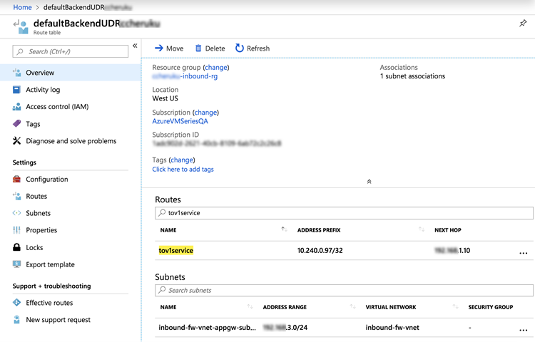
ILB behind the Application Gateway.In Azure, go to your inbound spoke resource group, view the route table and add a new route based on the destination service IP. In the following screen, the value in the tov1service ADDRESS PREFIX column is the service IP.
![]()
Connect the AKS Cluster in Azure Plugin for Panorama
This task assumes you have deployed a Panorama orchestrated
deployment, and that you have created templates, template stacks and device groups.
See
the Panorama online help for more on filling out each form.
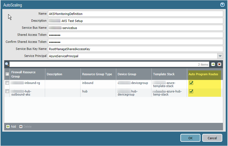
- Select PanoramaAzureDeployments to
view the monitoring definition you created when you configured the
deployment. As shown below, if Auto Program Routes is
enabled, the firewall routes are programmed for you.
![]()
- In AKS,
tag your Resource Groups. The tags are name/value pairs.
- Select HomeResource groups and choose a resource group.
- Select Tags and
define name/value pairs. As shown in the following figure, the tag names
must be inboundgrouprg and HubRG:
- inboundgrouprg—your spoke resource group name
- HubRG—your hub resource group name
![]() The template takes the name of the Spoke resource group as a parameter, and tags the VNet and AKS cluster with the Spoke resource group name so that it can be discovered by the Panorama plugin for Azure.
The template takes the name of the Spoke resource group as a parameter, and tags the VNet and AKS cluster with the Spoke resource group name so that it can be discovered by the Panorama plugin for Azure.
The templates deploy resources in separate VNets. If you manually deploy the AKS cluster and service in the same VNet as the Spoke firewall set, you must manually create tags for the spoke resource group name. - In Panorama, select PanoramaAzureSetup.
- On the General tab, enable monitoring.
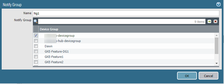
- On the Notify Groups tab, Add a
notification group and select the device groups to be notified.
![]()
- On the Service Principal tab, Add and Validate a
service principal.Use the Service Principal you created for the orchestrated deployment.
![]()
- On the AKS
Cluster tab, Add an AKS cluster.
- Enter the exact name of the AKS cluster.
- Enter the API server address. To find the address in Azure, view your AKS service and select Overview.
- Upload the AKS credential JSON file (see Create AKS Cluster Authentication).
- Fill in the remaining fields and Add one
or more tags.If you have service names or tags that are not unique across namespaces, use the label selector to filter both a tag and a namespace so that you get a unique result.
![]()
- Select PanoramaAzureMonitoring Definition
- Add a Monitoring definition.
- Enter a name and description, and select AKS Cluster Monitoring.
- Select an AKS Cluster and a Notify
Group, check Enable, and click OK.
![]()
Set Up VNet Peering
If you plan to use an address
group to identify traffic, be sure to add the subnet address group to
your top-level Panorama plicy before you configure peering.
After
deploying an AKS cluster, set up VNet Peering from
the Inbound VNet to your cluster, and from your cluster to the Firewall
VNet.
Redirect Traffic to a Firewall ILB
You must manually create user defined routes
(UDRs) and routing rules to redirect traffic to a particular ILB.
For an example, see how the diagram in “How Does the Panorama Plugin for Azure Secure Kubernetes Services?” depicts
an inbound UDR.
- Create URL routing rules that redirect web traffic to the appropriate backend pool.
- Update the UDR rules for the application gateway subnet to add a route for the service CIDR, with the next hop being the Inbound Firewall Load Balancer from the Spoke firewall resource group.
Apply Policy to Relevant AKS Service
- In Panorama, select Policies.
- In the Device Group list, choose the device group for your AKS service.
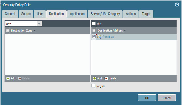
- Add a Security Policy rule. Fill
out the form, and on the Destination tab Add the
destination address or address group.
![]()
Deploy and Secure AKS Services
These steps outline how you can secure inbound
and outbound traffic traversing to Kubernetes services using VM-Series
firewall and the Azure Plugin for Panorama.
- In the application deployment environment, create
a YAML file for the application or use a file that already exists.
The following is a sample application YAML file:
apiVersion: apps/v1
kind: Deployment
metadata:
  name: azure-vote-back
spec:
  replicas: 1
  selector:
    matchLabels:
      app: azure-vote-back
  template:
    metadata:
      labels:
        app: azure-vote-back
    spec:
      containers:
      - name: azure-vote-back
        image: redis
        resources:
          requests:
            cpu: 100m
            memory: 128Mi
          limits:
            cpu: 250m
            memory: 256Mi
        ports:
        - containerPort: 6379
          name: redis
---
apiVersion: v1
kind: Service
metadata:
  name: azure-vote-back
  labels:
    service: backend
spec:
  ports:
  - port: 6379
  selector:
    app: azure-vote-back
---
apiVersion: apps/v1
kind: Deployment
metadata:
  name: azure-vote-front
spec:
  replicas: 5
  selector:
    matchLabels:
      app: azure-vote-front
  template:
    metadata:
      labels:
        app: azure-vote-front
    spec:
      containers:
      - name: azure-vote-front
        image: microsoft/azure-vote-front:v1
        resources:
          requests:
            cpu: 100m
            memory: 128Mi
          limits:
            cpu: 250m
            memory: 256Mi
        ports:
        - containerPort: 80
        env:
        - name: REDIS
          value: "azure-vote-back"
---
apiVersion: v1
kind: Service
metadata:
  name: azure-vote-front
  labels:
    service: "azure-vote-front"
    type: "production"
    providesecurity: "yes"
    a: "value"
    b: "value"
    c: "value"
    tier: "stagingapp"
  annotations:
    service.beta.kubernetes.io/azure-load-balancer-internal: "true"
spec:
  type: LoadBalancer
  ports:
  - port: 80
  selector:
    app: azure-vote-front
- Edit your YAML file to label Kubernetes services.Labels enable the corresponding tag-to-IP mapping to be created when you use the Panorama plugin for AKS to connect to the cluster. For example, in the above sample file look for the application labels in the service metadata. They are: azure-vote-back and azure-vote-front.
- In your AKS cluster, apply the YAML file.
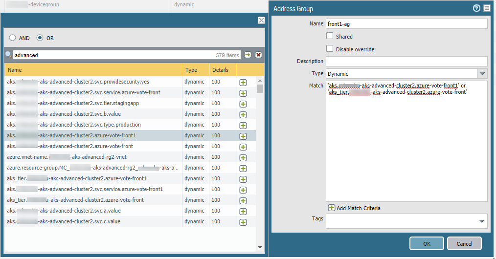
- In Panorama, create an Address Group using a resource group tag.
- On the Objects tab, select a device group from the Device Group list.
- Select Address Groups and Add an
Address Group.
- Specify a name, and select the Dynamic type.
- Add addresses. Adding spawns a window that lists detected addresses. Populating the list can take several minutes.
- You can choose one or more addresses for the Match Criteria. Select AND or OR for the criteria relationship.
- If you have many addresses, enter a string in the search box to filter the output, as shown in the following figure.
- In the address list, click the + to include the address in the address group match criteria.
- When the match criteria is complete, click OK.
![]()
- Show Policy using the address group.
![]()
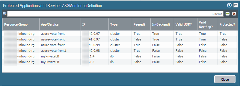
- View secured AKS services.In PanoramaAzureDeployments, view your monitoring definition, and in the Action column select the Protected Applications and Services link.The Protected? column summarizes the security status of your resource groups. It might take several minutes for the window to populate. If you have many resource groups, enter a string in the search box to filter the output.This output is based on the Azure resource group configuration; it does not query the device group or template stack membership.
![]()


