Take a Custom Packet Capture
Table of Contents
End-of-Life (EoL)
Take a Custom Packet Capture
Custom packet captures allow you to define
the traffic that the firewall will capture. To ensure that you capture
all traffic, you may need to Disable Hardware Offload.
- Before you start a packet capture, identify the attributes of the traffic that you want to capture.For example, to determine the source IP address, source NAT IP address, and the destination IP address for traffic between two systems, perform a ping from the source system to the to the destination system. After the ping is complete, go to MonitorTraffic and locate the traffic log for the two systems. Click the Detailed Log View icon located in the first column of the log and note the source address, source NAT IP, and the destination address.
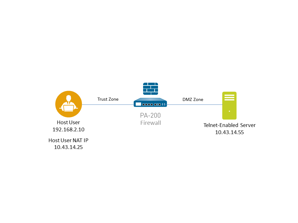
![]() The following example shows how to use a packet capture to troubleshoot a Telnet connectivity issue from a user in the Trust zone to a server in the DMZ zone.
The following example shows how to use a packet capture to troubleshoot a Telnet connectivity issue from a user in the Trust zone to a server in the DMZ zone.![]() Set packet capture filters, so the firewall only captures traffic you are interested in.Using filters makes it easier for you to locate the information you need in the packet capture and will reduce the processing power required by the firewall to take the packet capture. To capture all traffic, do not define filters and leave the filter option off.For example, if you configured NAT on the firewall, you will need to apply two filters. The first one filters on the pre-NAT source IP address to the destination IP address and the second one filters traffic from the destination server to the source NAT IP address.
Set packet capture filters, so the firewall only captures traffic you are interested in.Using filters makes it easier for you to locate the information you need in the packet capture and will reduce the processing power required by the firewall to take the packet capture. To capture all traffic, do not define filters and leave the filter option off.For example, if you configured NAT on the firewall, you will need to apply two filters. The first one filters on the pre-NAT source IP address to the destination IP address and the second one filters traffic from the destination server to the source NAT IP address.- Select MonitorPacket Capture.Click Clear All Settings at the bottom of the window to clear any existing capture settings.Click Manage Filters and click Add.Select Id 1 and in the Source field enter the source IP address you are interested in and in the Destination field enter a destination IP address.For example, enter the source IP address 192.168.2.10 and the destination IP address 10.43.14.55. To further filter the capture, set Non-IP to exclude non-IP traffic, such as broadcast traffic.Add the second filter and select Id 2.For example, in the Source field enter 10.43.14.55 and in the Destination field enter 10.43.14.25. In the Non-IP drop-down menu select exclude.
![]() Click OK.Set Filtering to On.Specify the traffic stage(s) that trigger the packet capture and the filename(s) to use to store the captured content. For a definition of each stage, click the Help icon on the packet capture page.For example, to configure all packet capture stages and define a filename for each stage, perform the following procedure:
Click OK.Set Filtering to On.Specify the traffic stage(s) that trigger the packet capture and the filename(s) to use to store the captured content. For a definition of each stage, click the Help icon on the packet capture page.For example, to configure all packet capture stages and define a filename for each stage, perform the following procedure:- Add a Stage to the packet capture configuration and define a File name for the resulting packet capture.For example, select receive as the Stage and set the File name to telnet-test-received.
![]() Continue to Add each Stage you want to capture (receive, firewall, transmit, and drop) and set a unique File name for each stage.
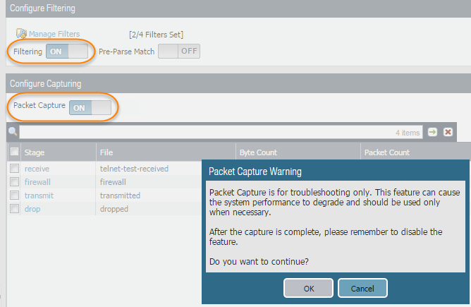
Continue to Add each Stage you want to capture (receive, firewall, transmit, and drop) and set a unique File name for each stage.![]() Set Packet Capture to ON.The firewall or appliance warns you that system performance can be degraded; acknowledge the warning by clicking OK. If you define filters, the packet capture should have little impact on performance, but you should always turn Off packet capture after the firewall captures the data that you want to analyze.
Set Packet Capture to ON.The firewall or appliance warns you that system performance can be degraded; acknowledge the warning by clicking OK. If you define filters, the packet capture should have little impact on performance, but you should always turn Off packet capture after the firewall captures the data that you want to analyze.![]() Generate traffic that matches the filters that you defined.For this example, generate traffic from the source system to the Telnet-enabled server by running the following command from the source system (192.168.2.10):telnet 10.43.14.55Turn packet capture OFF and then click the refresh icon to see the packet capture files.
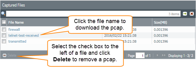
Generate traffic that matches the filters that you defined.For this example, generate traffic from the source system to the Telnet-enabled server by running the following command from the source system (192.168.2.10):telnet 10.43.14.55Turn packet capture OFF and then click the refresh icon to see the packet capture files.![]() Notice that in this case, there were no dropped packets, so the firewall did not create a file for the drop stage.Download the packet captures by clicking the filename in the File Name column.
Notice that in this case, there were no dropped packets, so the firewall did not create a file for the drop stage.Download the packet captures by clicking the filename in the File Name column.![]() View the packet capture files using a network packet analyzer.In this example, the received.pcap packet capture shows a failed Telnet session from the source system at 192.168.2.10 to the Telnet-enabled server at 10.43.14.55. The source system sent the Telnet request to the server, but the server did not respond. In this example, the server may not have Telnet enabled, so check the server.
View the packet capture files using a network packet analyzer.In this example, the received.pcap packet capture shows a failed Telnet session from the source system at 192.168.2.10 to the Telnet-enabled server at 10.43.14.55. The source system sent the Telnet request to the server, but the server did not respond. In this example, the server may not have Telnet enabled, so check the server.![]() Enable the Telnet service on the destination server (10.43.14.55) and turn on packet capture to take a new packet capture.Generate traffic that will trigger the packet capture.Run the Telnet session again from the source system to the Telnet-enabled servertelnet 10.43.14.55Download and open the received.pcap file and view it using a network packet analyzer.The following packet capture now shows a successful Telnet session from the host user at 192.168.2.10 to the Telnet-enabled server at 10.43.14.55.You also see the NAT address 10.43.14.25. When the server responds, it does so to the NAT address. You can see the session is successful as indicated by the three-way handshake between the host and the server and then you see Telnet data.
Enable the Telnet service on the destination server (10.43.14.55) and turn on packet capture to take a new packet capture.Generate traffic that will trigger the packet capture.Run the Telnet session again from the source system to the Telnet-enabled servertelnet 10.43.14.55Download and open the received.pcap file and view it using a network packet analyzer.The following packet capture now shows a successful Telnet session from the host user at 192.168.2.10 to the Telnet-enabled server at 10.43.14.55.You also see the NAT address 10.43.14.25. When the server responds, it does so to the NAT address. You can see the session is successful as indicated by the three-way handshake between the host and the server and then you see Telnet data.![]()


